In a previous post, we added an AXI timer to create a periodic interrupt. In this tutorial we are going to add support for the OLED screen to the WAV player project. This makes it a fully self-contained application which can be used without a PC.
In this tutorial we learn:
- How the OLED display is controlled.
- How we can reuse the SPI core to talk to the OLED display.
- How to use the slice blocks to split bus signals.
- How to write a driver allowing character output.
The OLED Display on the Zedboard
There is a surprising lack of documentation regarding the OLED display which comes with the Zedboard. There are examples sprinkled across the internet which are a good starting point to reverse engineer the protocol. Also quite a few larger OLED displays use the same controller so those datasheets apply to the small 128×32 pixel display as well. I found the collections at Adafruit helpful although they are mostly for different displays:
https://learn.adafruit.com/monochrome-oled-breakouts/downloads
https://cdn-shop.adafruit.com/datasheets/UG-2832HSWEG04.pdf
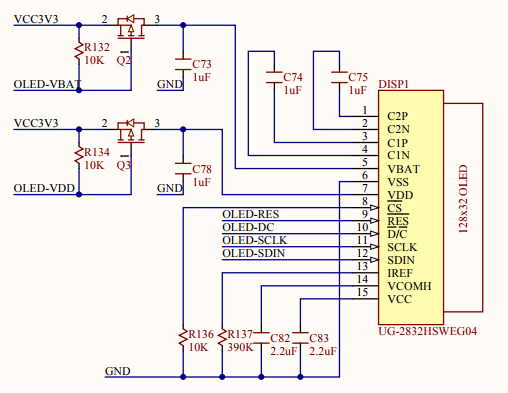
The display can be powered down using the signals oled_vbat and oled_vdd. The signals oled_sclk, oled_sdin, oled_dc are forming an SPI interface. The signal oled_res resets the controller.
Here is the relevant schematic:
Open the Main Project
- Start with the project from this post. Or download the complete project further down.
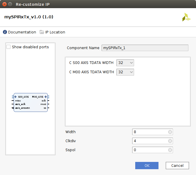
- To connect the SPI interface, we can use the same SPI controller we already created in a previous post. Add a mySPIRxTx_v1.0 core to the design.
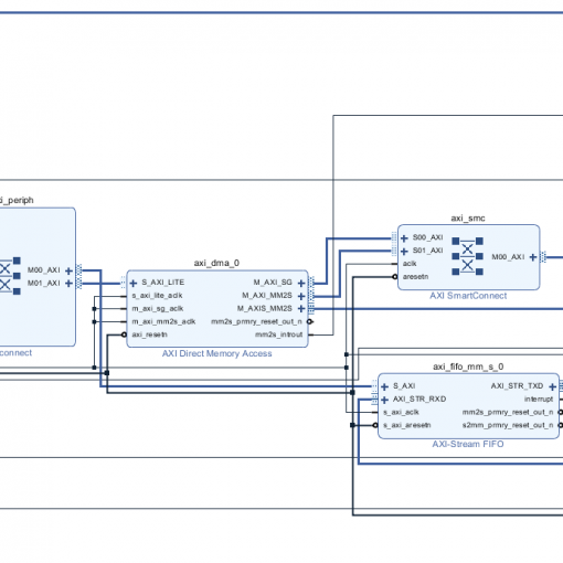
- Add an AXI Stream-FIFO to the design:
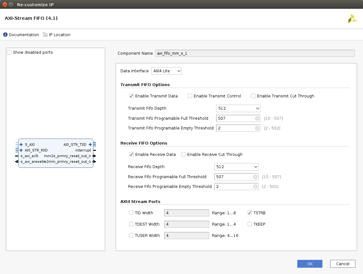
- Connect the FIFO’s AXI_STR_TXD port to the SPI core’s S00_AXIS port. Connect AXI_STR_RXD to M00_AXIS.
- We are not using the MISO input. Therefore, we are going to apply a constant value. There is an IP core called “constant”. Add this to the design and configure it like this:
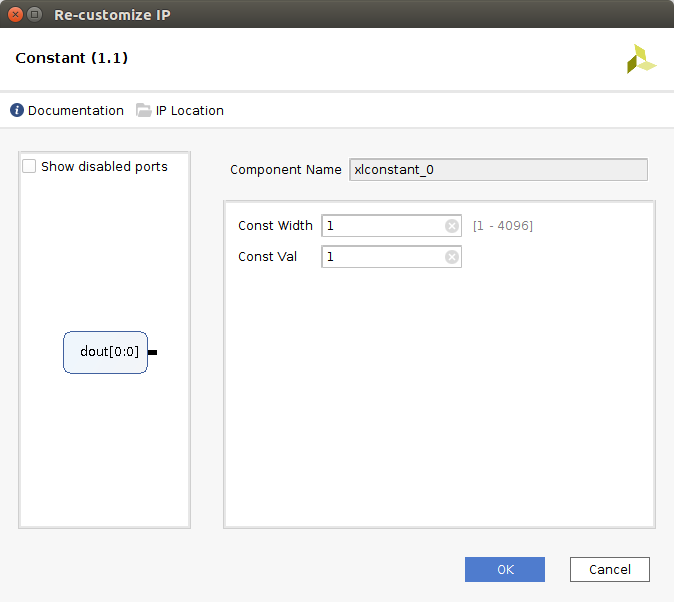
- Now connect the constant output to the MISO input of the SPI core.
- Right-click on the sclk output and click “Make external”. Rename the external port to oled_sclk.
- Right-click on the mosi output and click “Make external”. Rename the external port to oled_sdin.
- Run Connection Automation on the AXI port of the FIFO and the clock inputs of the SPI core.
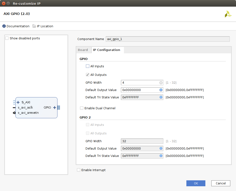
- There are four more signals which we need to generate. We will use an AXI GPIO block. Add it to the design and configure it like this:
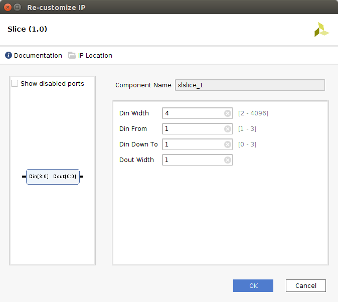
- The GPIO creates an output vector. Unfortunately, there is no easy way to demultiplex the individual signals. We are going to use four of the “slice” cores. Add the first “slice” core and configure it like this:

- Connect the input to the GPIO, make the output external and rename it to oled_vbat.
- Add another slice core and configure it like this:

- Connect the input to the GPIO, make the output external and rename it to oled_res.
- Add another slice core and configure it like this:

- Connect the input to the GPIO, make the output external and rename it to oled_dc.
- Add another slice core and configure it like this:
- Connect the input to the GPIO, make the output external and rename it to oled_vdd.
These are the additional pin definitions which need to be added to myConstraints.xdc:
set_property PACKAGE_PIN U10 [get_ports {oled_dc[0]}]
set_property IOSTANDARD LVCMOS33 [get_ports {oled_dc[0]}]
set_property PACKAGE_PIN U9 [get_ports {oled_res[0]}]
set_property IOSTANDARD LVCMOS33 [get_ports {oled_res[0]}]
set_property PACKAGE_PIN AB12 [get_ports oled_sclk]
set_property IOSTANDARD LVCMOS33 [get_ports oled_sclk]
set_property PACKAGE_PIN AA12 [get_ports oled_sdin]
set_property IOSTANDARD LVCMOS33 [get_ports oled_sdin]
set_property PACKAGE_PIN U11 [get_ports {oled_vbat[0]}]
set_property IOSTANDARD LVCMOS33 [get_ports {oled_vbat[0]}]
set_property PACKAGE_PIN U12 [get_ports {oled_vdd[0]}]
set_property IOSTANDARD LVCMOS33 [get_ports {oled_vdd[0]}]
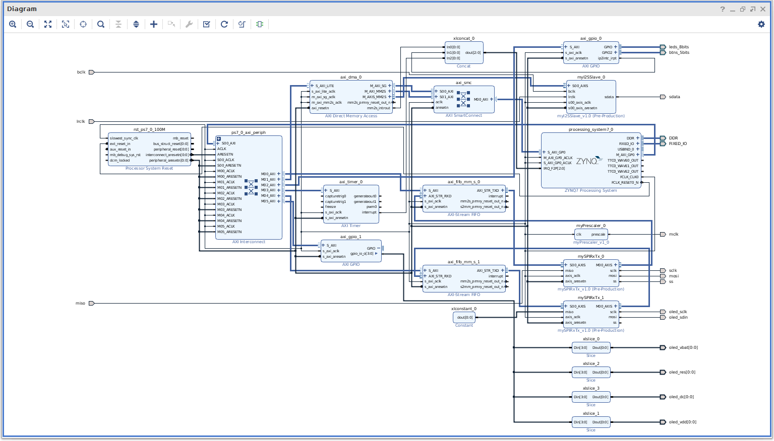
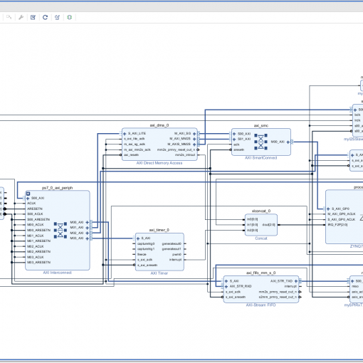
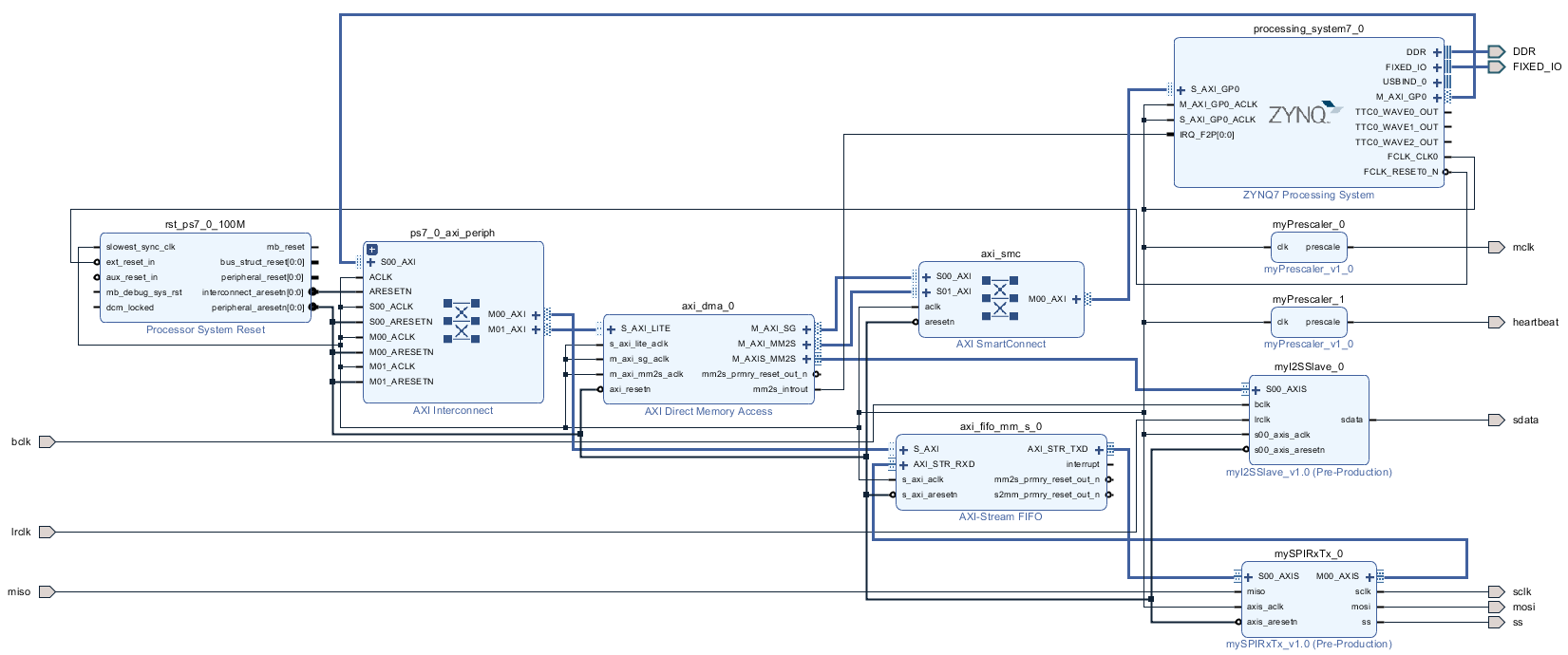
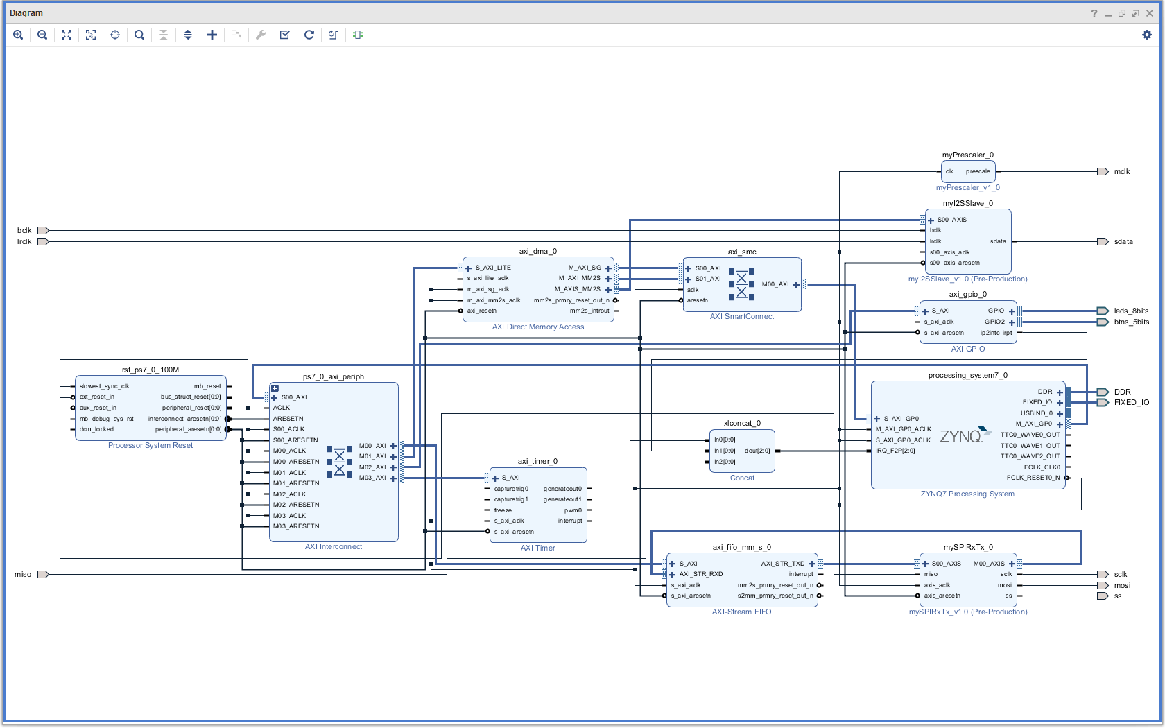
The Complete Block Diagram
Create the Bitstream
- Generate the bitstream.
- Open the Implementation.
- Export Hardware (including bitstream).
Modify the C-Code
- Launch the SDK. I encountered problems occasionally that the SDK creates a new system wrapper project. Normally there is a project named design_1_wrapper_hw_platform_0. I then have two of those. The second one named design_1_wrapper_hw_platform_1.
- Here is the full modified code (helloworld.c, oled.c, oled.h):

- Run the program with an SD card inserted:
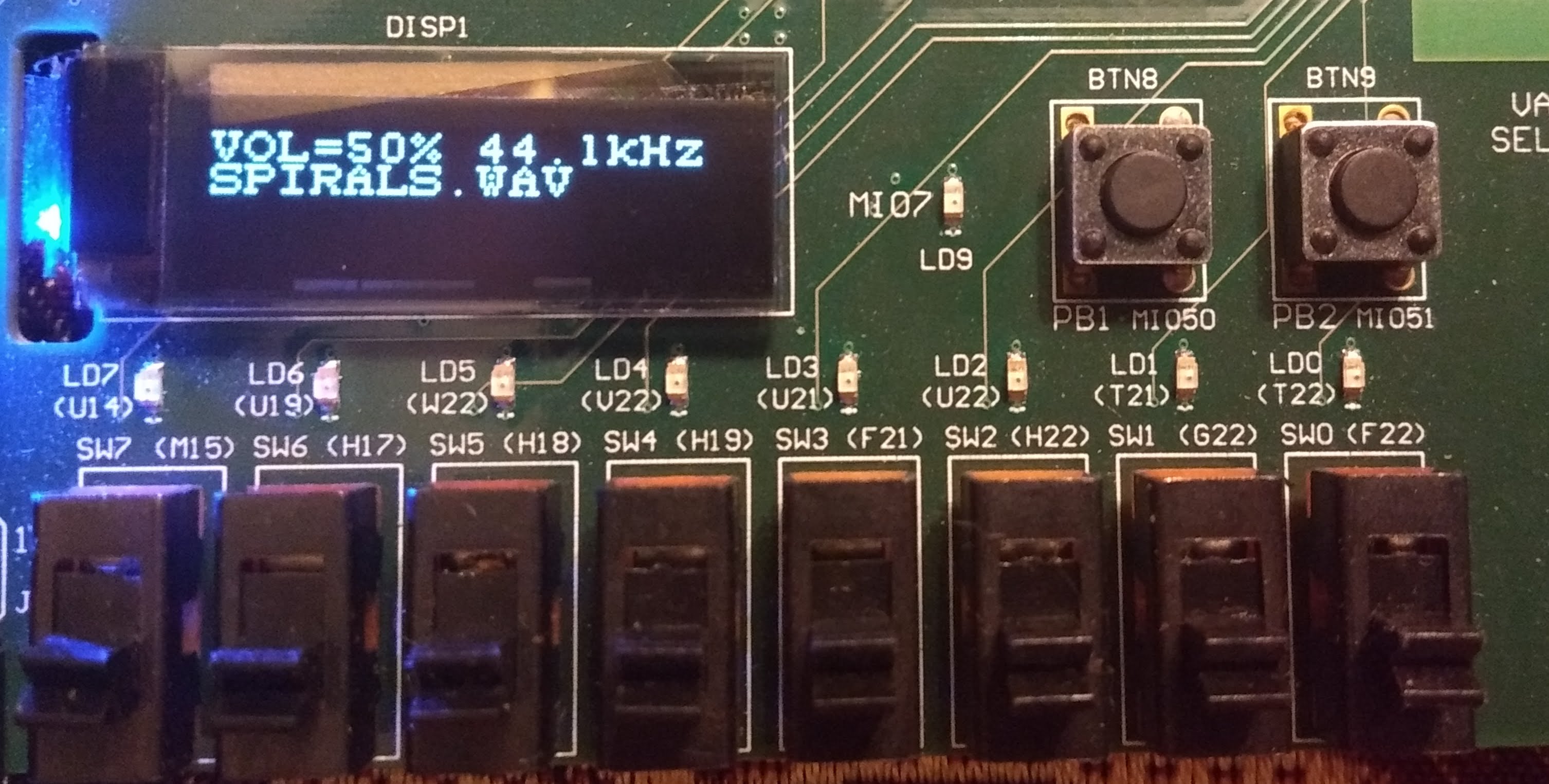
-
You can now use the keypad on the Zedboard to navigate up and down. Use left/right to change the volume. Use the middle button to play. Note that the keys are repeated when you hold them down for long enough.
- If the SD card is removed, the program jumps back to mounting an SD card. It will automatically detect when an SD card is inserted.
Download the Complete Project
- Here is a WAV file which I have tested (from the Youtube Audio Library):
- piano.wav
Piano March by Audionautix is licensed under a Creative Commons Attribution license (https://creativecommons.org/licenses/by/4.0/). Artist: http://audionautix.com/ - To upload the software to the Zedboard, open the project in Vivado, then click on “Launch SDK”.
- There seems to be a bug when updating the SDK project which selects a wrong UART driver (refer to “SDK Auto Update Bug” to fix it).
- Select the project CodecDMADemoOneshot and click “Run” (the “play” button at the top of the window).