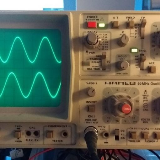
Want to probe signals? Just use the built-in logic tester.
OK. It’s not quite a replacement for a real logic tester. But it is immensely useful. For debugging purposes, you can add Debug Cores to the FPGA which record digital signals into on-chip memory (probably block RAM). You can use Vivado to display the results in a nice graph window. You can even setup trigger conditions including pre-trigger intervals.
Here is something to consider:
- The Debug Cores take space in the FPGA. If you have a large design, they may not fit.
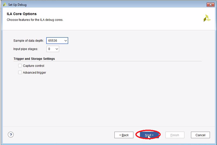
- Memory depth is limited to 128kSamples max.
- Advantage over an external logic tester: You can probe signals at the full clock rate. With an external logic tester, it can be hard to get good results probing external signals which are faster than 50MHz.
- Advantage over an external logic tester: You have access to internal signals (e.g. state machine states, counters etc.).
In this tutorial we will learn
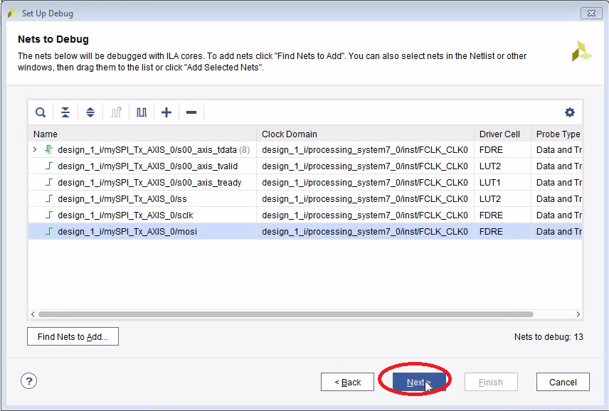
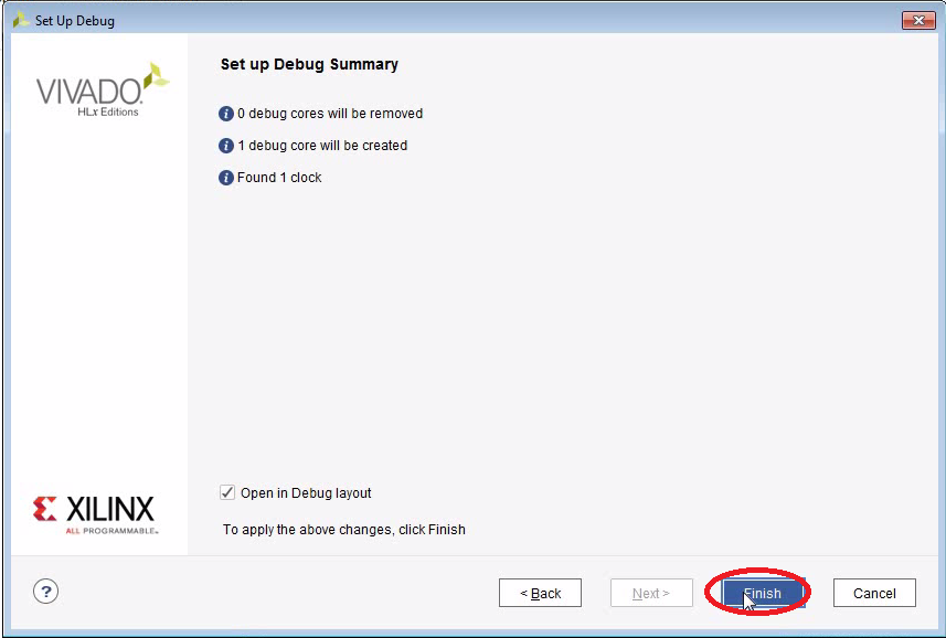
- How to add Debug Cores to your FPGA so you can use Vivado’s built-in logic-analyzer.
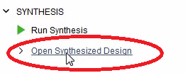
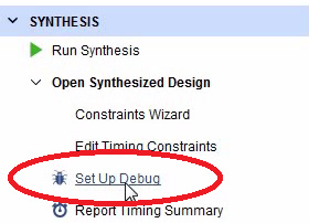
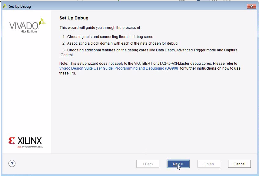
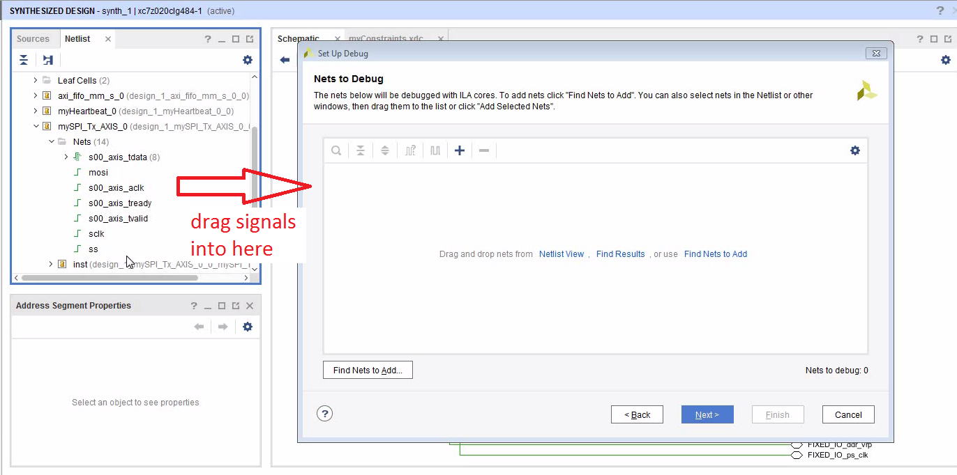
Add Debug Cores to Your Design


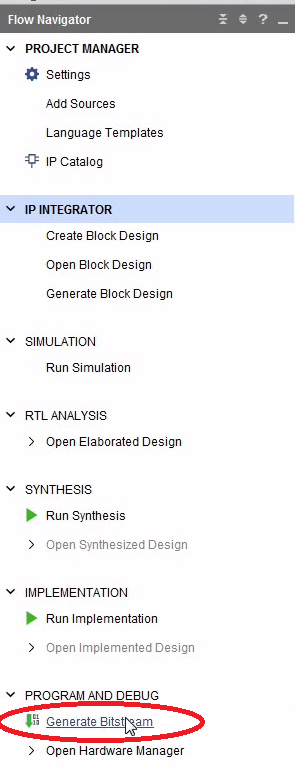
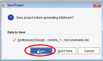
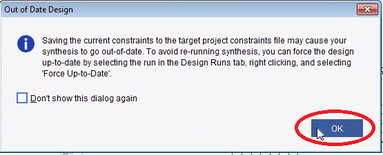
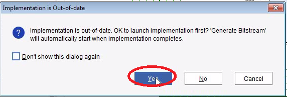
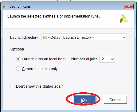
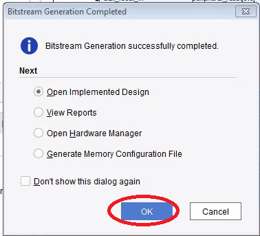
Generate Bitstream
- Be aware that the synthesis and the implementation will take a few minutes to run.
- After the bitstream has been created, we open the Implemented Design.
- For the next step it seems to be important that you have opened the implemented design.


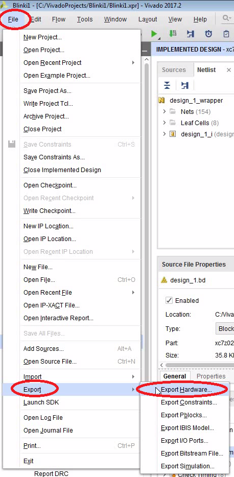
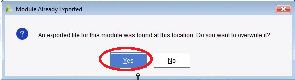
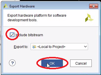
Export the Hardware to the SDK
- We need to update the SDK project with our changes (most notably the bitstream)
- So, let’s export the hardware and then open the SDK.


SDK Auto Update Bug?
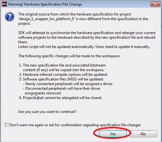
- If you have the SDK still open, it will detect the new files and it will want to update the system wrapper and the board-support project.
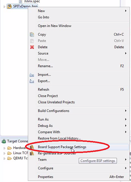
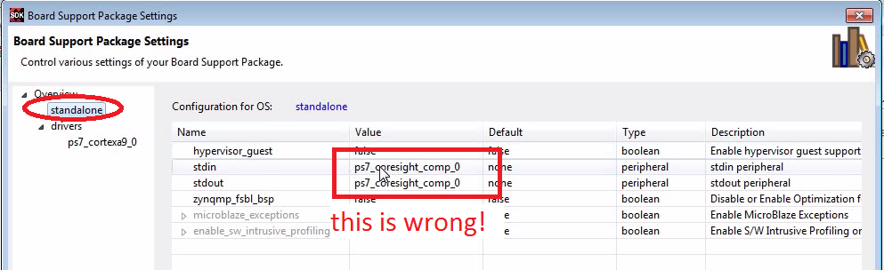
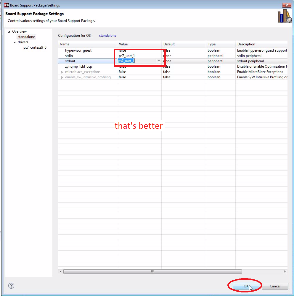
- Unfortunately this keeps messing up the UART settings. You might have to manually go into the Board Support Package Settings and choose “ps7_uart_1” for stdin/stdout. For some reason it is set to “ps7_coresight_comp_0”.
- Hint: This becomes really annoying since all C-projects get recompiled every time I change the bitstream. So, if I am sure that only the bitstream has changed, I copy it manually from the Vivado project into the SDK project (just search for *.bit files to work out the locations).


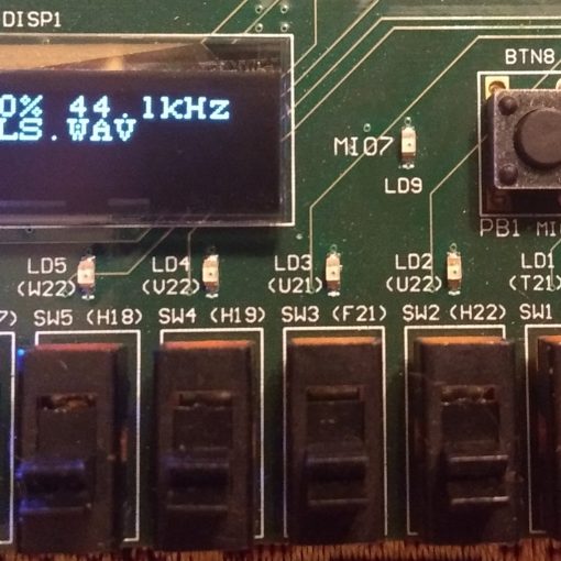
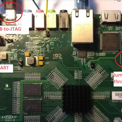
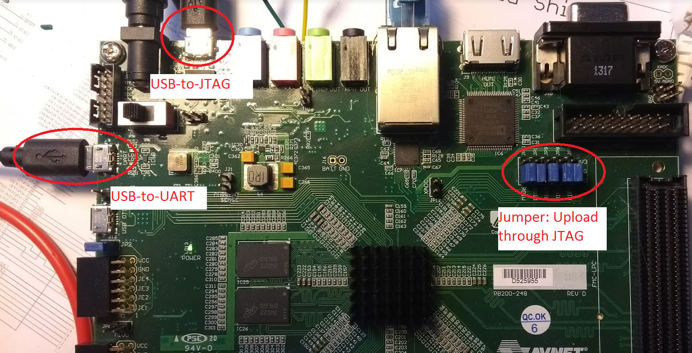
Connect Hardware and run Tera Term
- Refer to here on how to setup the jumpers and how to run Tera Term.
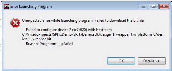
- Hint: If the board has been programmed with an old design, you may have to power-cycle the Zedboard. Otherwise you will get an unspecific error message.

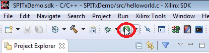
Run the Program
- The bitstream as well as the compiled C-program will be uploaded.
- Make sure that the project SPITxDemo is selected when clicking on the “Run” button.
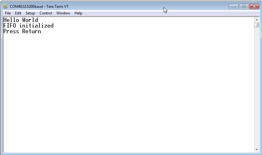
- You should see “Hello World” in the terminal.


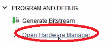
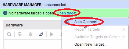
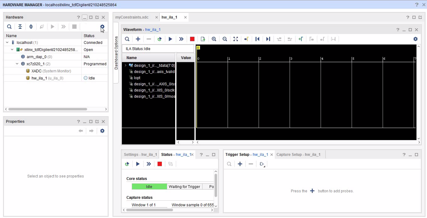
Open the Hardware Manager
- When Vivado connects through the JTAG to a running FPGA, it will automatically detect that there are Debug Cores running.
- It will then show the timing-diagram window.


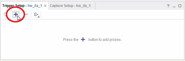
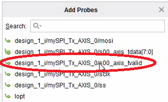
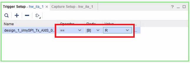
Setup the Data Acquisition
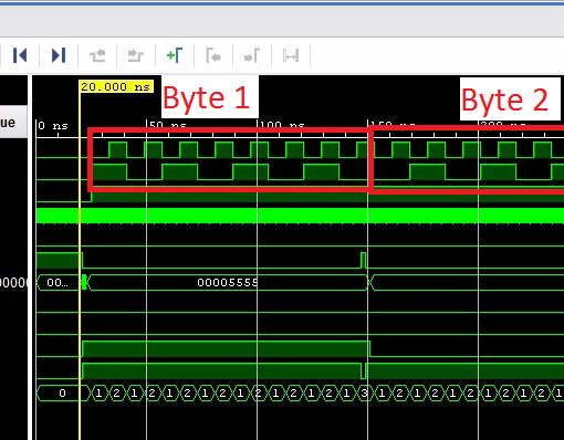
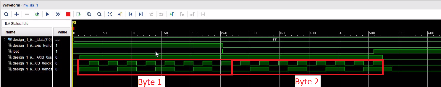
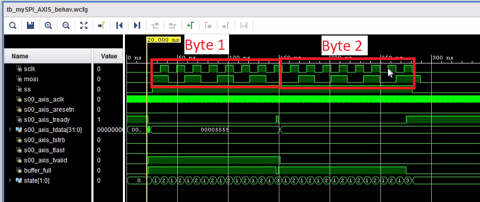
- A high-transition of TVALID indicates a write-cycle to the AXI stream interface. So, let’s trigger on the rising edge.


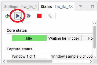
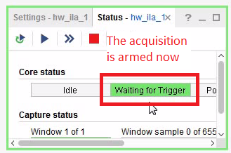
Start the Data Acquisition
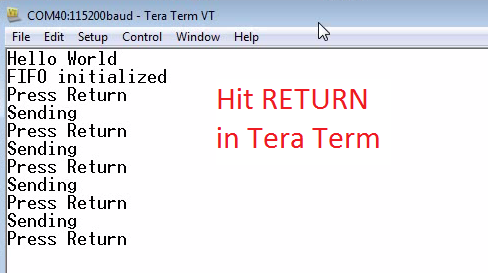
- After the acquisition is armed, hit RETURN in Tera Term. That initiates a two-word transfer by putting two words into the FIFO.


Download the Complete Project

Next: Using the Audio Codec (Bidirectional SPI IP-Core)
- This example was simplified as it was only transmitting data. However, a real SPI interface receives a byte for any transmitted byte.
- The next tutorial shows how to make a bidirectional SPI Interface.
- It also shows how to talk to the on-board audio codec.