In a previous post, we made a simple WAV file player which feeds the DMA controller from an interrupt routine. Currently the player is controller through the terminal connected to the UART. The Zedboard has LEDs and buttons which we can use as user interface. So let’s create a simple user interface which can be used without a PC connected.
In this tutorial we learn:
- How to set up an AXI GPIO interface.
- How to connect a second interrupt signal to the ZYNQ fabric.
- How to add a second interrupt handler.
Interfacing to the AXI GPIO
- Use the include file xgpio.h.
- Use the object XGpio to interface to the GPIO controller.
- The first device ID is XPAR_AXI_GPIO_0_DEVICE_ID (defined in xparameters.h).
- The corresponding interrupt ID is XPAR_FABRIC_AXI_GPIO_0_IP2INTC_IRPT_INTR (defined in xparameters.h).
Open the Main Project
- Start with the project from this post. Or download the complete project further down.
- Remove the prescaler which is connected to the heartbeat LED. We need all 8 LEDs to form a bar graph display. Also remove the heartbeat output.
- Add an AXI GPIO IP core and configure it:
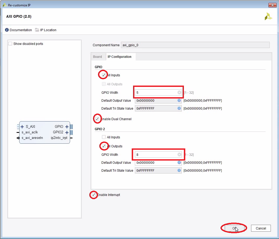
- Connect the board LEDs to the GPIO block (drag them over into the block design):

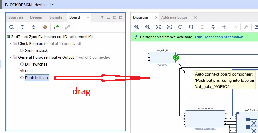
- Do the same thing with the push buttons:
- Note that Vivado has changed the order of the ports. The first port is now the output although we configured the first port to be an input. That’s probably a feature, not a bug…
- I found that you can only connect the LEDs and the buttons if the width of the interfaces are exactly right. I did not manage to connect only 3 bits of the LED vector using the drag-and-drop method. I had to resort to the constraint file instead and assign the pin numbers and logic levels manually.
- Run Connection Automation.
- To connect a second interrupt signal to the IRQ_F2P[] input we need to add a concat block. The concat block merges the two interrupt signals into a 2-bit vector. Note that you can still connect it to IRQ_F2P[0:0]. When you run the synthesis, Vivado will change it to IRQ_F2P[0:1]:
- Disconnect the interrupt output of the DMA controller.
- Add the concat block.
- Connect the interrupt output of the DMA controller to the first input of the concat block.
- Connect the interrupt output of the GPIO to the second input of the concat block.
- Connect the output of the concat block to IRQ_F2P[].
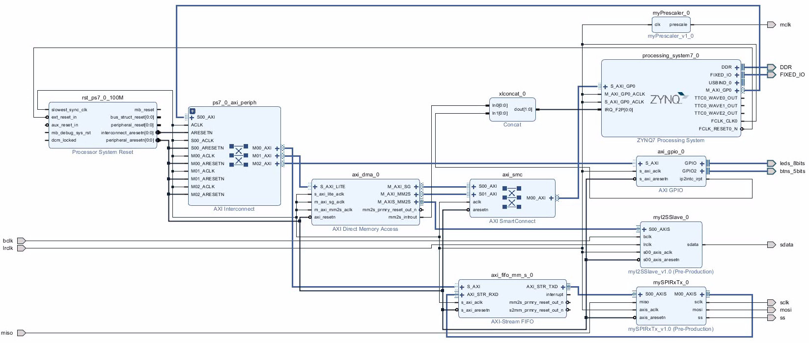
The Complete Block Diagram
Create the Bitstream
- Generate the bitstream.
- Open the Implementation.
- Export Hardware (including bitstream).
Modify the C-Code
- Launch the SDK. I encountered problems occasionally that the SDK creates a new system wrapper project. Normally there is a project named design_1_wrapper_hw_platform_0. I then have two of those. The second one named design_1_wrapper_hw_platform_1.
- Here is the full modified code (helloworld.c):

- Run the program with an SD card inserted:
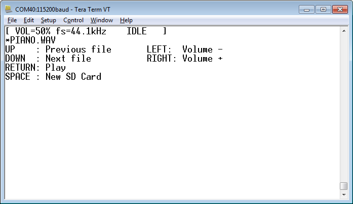
- You can now use the keypad on the Zedboard to navigate up and down. Use left/right to change the volume. Use the middle button to play.
- The 8 LEDs are now used as a progress indicator.
Download the Complete Project
- Here is a WAV file which I have tested (from the Youtube Audio Library):
- piano.wav
Piano March by Audionautix is licensed under a Creative Commons Attribution license (https://creativecommons.org/licenses/by/4.0/). Artist: http://audionautix.com/ - To upload the software to the Zedboard, open the project in Vivado, then click on “Launch SDK”.
- There seems to be a bug when updating the SDK project which selects a wrong UART driver (refer to “SDK Auto Update Bug” to fix it).
- Select the project CodecDMADemoOneshot and click “Run” (the “play” button at the top of the window).
Next: Adding an AXI Timer to Trigger Periodic Interrupts
It is normally a better choice to scan a keyboard in a periodic interrupt. The next tutorial shows how to add an AXI timer which triggers a periodic interrupt every 20 ms:
