AXI Interfaces are awesome because you can connect wires to them.
AXI interfaces are widely used within the Xilinx and ARM ecosystem. I found it’s well worth the time to write your own code using these standard interfaces because it allows you to connect to existing infrastructure. It is, for example, very easy to map an IP core with an AXI interface into the address space of the ARM microcontroller.
There are two main AXI interfaces: Standard and Stream. The Standard interface is a parallel interface with lots of address and data signals (like in the olden days of microprocessors). The Stream interface does not use addresses. It is a glorified parallel data bus with some clock and handshake. I believe the AXI Stream interface is the simplest AXI interface. You can easily connect it to existing IP cores which can map it into memory, add FIFOs or DMA capability.
In this tutorial we will learn:
- How to use a wizard to create a custom IP core with an AXI Stream interface.
- How to implement a simple SPI transmitter (SCLK, MOSI, SS).
- How to simulate the behaviour using a test bench.
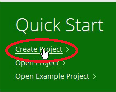
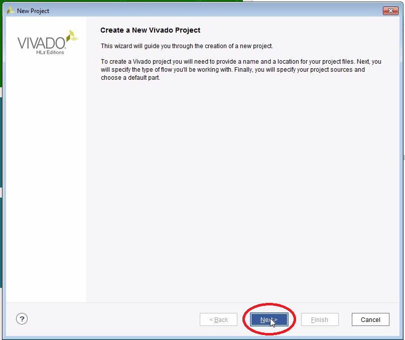
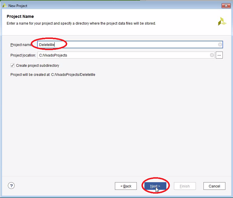
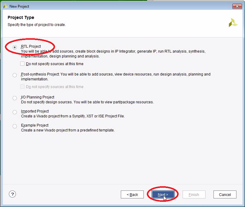
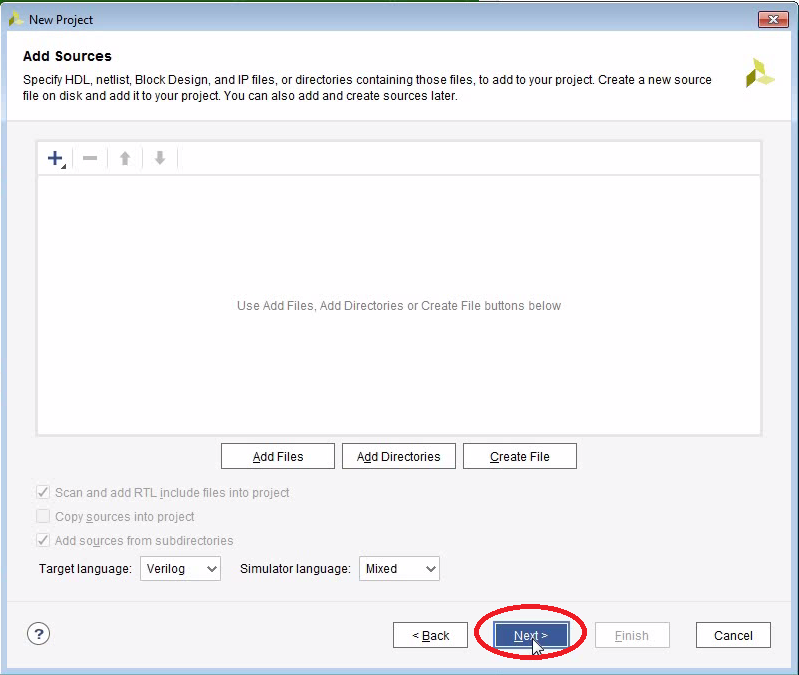
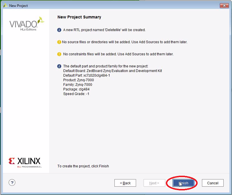
Let’s Create a Throw-Away Project


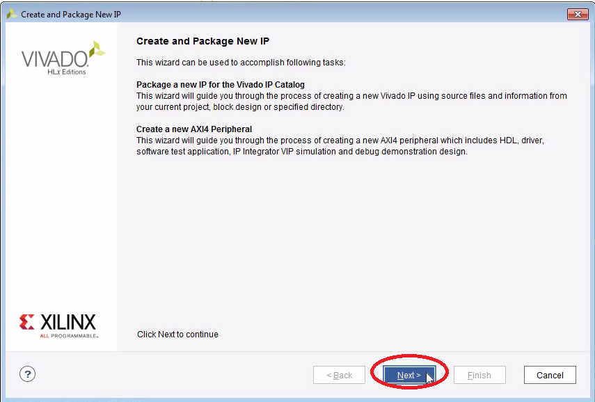
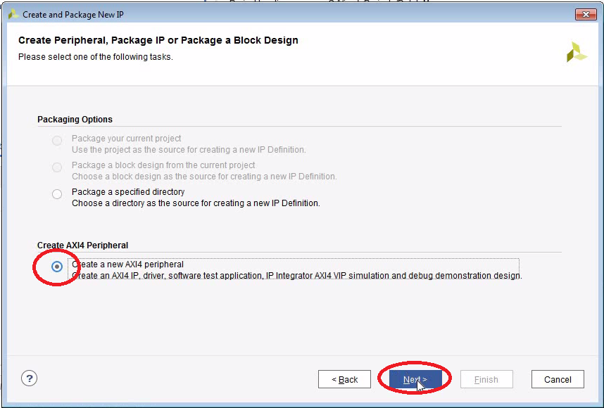
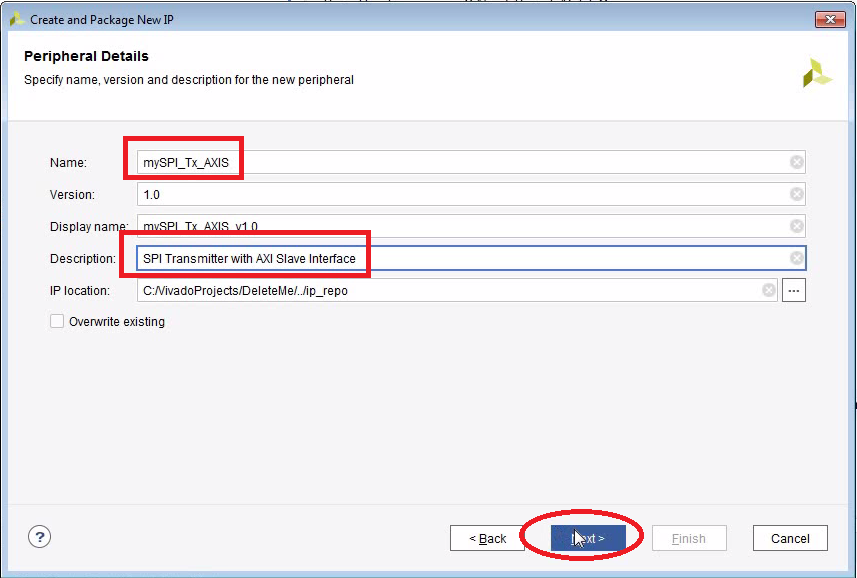
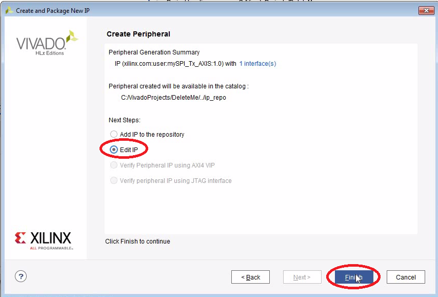
Create an IP Core With an AXI Stream Interface
- The IP Core will end up at a fairly random location. Just go with it, we will copy it later to the desired location.


Implement the SPI Interface
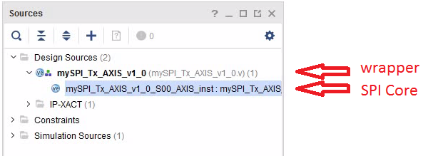
- The wizard creates two Verilog files: A wrapper (mySPI_Tx_AXIS_v1_0.v) and the actual IP core (mySPI_Tx_AXIS_v1_0_S00_AXIS.v).
- The wizard also adds a default implementation with a FIFO. In this example we are not going to use that.
- Edit the two files and replace the contents with the two source codes below.
mySPI_Tx_AXIS_v1_0.v
`timescale 1 ns / 1 ps

	module mySPI_Tx_AXIS_v1_0 #
	(
		// Users to add parameters here
        parameter integer width	= 8,
        parameter integer clkdiv= 4,

		// User parameters ends
		// Do not modify the parameters beyond this line


		// Parameters of Axi Slave Bus Interface S00_AXIS
		parameter integer C_S00_AXIS_TDATA_WIDTH	= 32
	)
	(
		// Users to add ports here
        output wire sclk,
        output wire mosi,
        output wire ss,

		// User ports ends
		// Do not modify the ports beyond this line


		// Ports of Axi Slave Bus Interface S00_AXIS
		input wire  s00_axis_aclk,
		input wire  s00_axis_aresetn,
		output wire  s00_axis_tready,
		input wire [C_S00_AXIS_TDATA_WIDTH-1 : 0] s00_axis_tdata,
		input wire [(C_S00_AXIS_TDATA_WIDTH/8)-1 : 0] s00_axis_tstrb,
		input wire  s00_axis_tlast,
		input wire  s00_axis_tvalid
	);

    // Instantiation of Axi Bus Interface S00_AXIS
	mySPI_Tx_AXIS_v1_0_S00_AXIS # (
        .width(width),
        .clkdiv(clkdiv),
		.C_S_AXIS_TDATA_WIDTH(C_S00_AXIS_TDATA_WIDTH)
	) mySPI_Tx_AXIS_v1_0_S00_AXIS_inst (
        .sclk(sclk),
        .mosi(mosi),
        .ss(ss),
		.S_AXIS_ACLK(s00_axis_aclk),
		.S_AXIS_ARESETN(s00_axis_aresetn),
		.S_AXIS_TREADY(s00_axis_tready),
		.S_AXIS_TDATA(s00_axis_tdata),
		.S_AXIS_TSTRB(s00_axis_tstrb),
		.S_AXIS_TLAST(s00_axis_tlast),
		.S_AXIS_TVALID(s00_axis_tvalid)
	);

	// Add user logic here

	// User logic ends

	endmodule
mySPI_Tx_AXIS_v1_0_S00_AXIS.v
`timescale 1 ns / 1 ps

	module mySPI_Tx_AXIS_v1_0_S00_AXIS #
	(
		// Users to add parameters here
        parameter integer width	= 8,
        parameter integer clkdiv= 4,

		// User parameters ends
		// Do not modify the parameters beyond this line

		// AXI4Stream sink: Data Width
		parameter integer C_S_AXIS_TDATA_WIDTH	= 32
	)
	(
		// Users to add ports here
        output wire sclk,
        output reg mosi = 0,
        output wire ss,

		// User ports ends
		// Do not modify the ports beyond this line

		// AXI4Stream sink: Clock
		input wire  S_AXIS_ACLK,
		// AXI4Stream sink: Reset
		input wire  S_AXIS_ARESETN,
		// Ready to accept data in
		output wire  S_AXIS_TREADY,
		// Data in
		input wire [C_S_AXIS_TDATA_WIDTH-1 : 0] S_AXIS_TDATA,
		// Byte qualifier
		input wire [(C_S_AXIS_TDATA_WIDTH/8)-1 : 0] S_AXIS_TSTRB,
		// Indicates boundary of last packet
		input wire  S_AXIS_TLAST,
		// Data is in valid
		input wire  S_AXIS_TVALID
	);

	// This holds the shift register
	reg [width-1 : 0] buffer = 0;
	reg buffer_full = 0;

    // Counts the bits
	reg [5:0] bitcounter = 0;

	// Makes things slower
	reg [clkdiv-1:0] prescaler = 0;

    // State machine states
    localparam IDLE = 0;
    localparam S1 = 1;
    localparam S2 = 2;
    localparam S3 = 3;

    // Default state is IDLE
    reg [1:0] state = IDLE;

    // Signals we are ready to receive
	assign S_AXIS_TREADY = !buffer_full;

	// SPI Clock (data is valid during Low/High transition)
	assign sclk = state==S2 || state==S3;

	// SPI Slave Select
	assign ss = state!=IDLE;

	// This is the main state machine
    always @(posedge S_AXIS_ACLK) begin
        // There is only one important rule for an AXI Stream interface:
        // If during the rising clock, S_AXIS_TVALID==1 and S_AXIS_TREADY==1, then we have to accept the data.
        if (S_AXIS_TVALID==1 && S_AXIS_TREADY==1) begin
            buffer <= S_AXIS_TDATA[width-1 : 0];
            buffer_full = 1;
        end else if (state==S3 && prescaler==1) begin
            buffer_full = 0;
        end

        prescaler <= prescaler+1;
        if (prescaler==0) begin // The state transitions are synchronized to the SPI bit clock
            case(state)
                IDLE:   begin // ss=0, sclk=0, mosi=0
                            mosi <= 0;
                            if (buffer_full==1) begin
                                mosi <= buffer[width-1];
                                bitcounter <= 1;
                                state <= S1;
                            end
                        end
                S1:     begin // ss=1, sclk=0
                            if ( bitcounter==width ) begin
                                state <= S3;
                            end else begin
                                state <= S2;
                                buffer <= buffer<<1;
                            end
                        end
                S2:     begin // ss=1, sclk=1
                            state <= S1;
                            mosi <= buffer[width-1];
                            bitcounter <= bitcounter+1;
                        end
                S3:     begin // ss=1, sclk=1 (last bit)
                            if (buffer_full==1) begin
                                mosi <= buffer[width-1];
                                bitcounter <= 1;
                                state <= S1;
                            end else begin
                                state <= IDLE;
                            end
                        end
                default:begin
                            state <= IDLE;
                        end
            endcase
        end
    end

	endmodule
AXI Stream Interface (Oversimplified)
Here is a very simple view on the AXI Stream interface.
It consists of the following signals:
- ACLK
- Master-to-Slave: TDATA (e.g. 32 bits wide)
- Master-to-Slave: TVALID
- Slave-to-Master: TREADY
There are two simple rules:
- All transitions happen on the rising edge of ACLK.
- The slave (e.g. the SPI transmitter) will accept data only when this is true: TVALID=1 and TREADY=1 during a high-transition of the clock. Then (and only then) the data at TDATA is accepted by the slave.
The master observes this condition as well and thus knows when the data has been accepted by the slave. A transfer would look like this:
- The master applies the data to TDATA and asserts TVALID
- Then waits for TVALID=1 and TREADY=1. Once that condition occurred, the master can either de-assert TVALID (otherwise the data would be written twice) or apply the next data to TDATA and keep TVALID asserted.
- The slave accepts data in case TVALID=1 and TREADY=1. If the slave will not be ready to accept data at the next positive clock, it is important to de-assert TREADY. Otherwise the master could send the next data at the next clock edge.
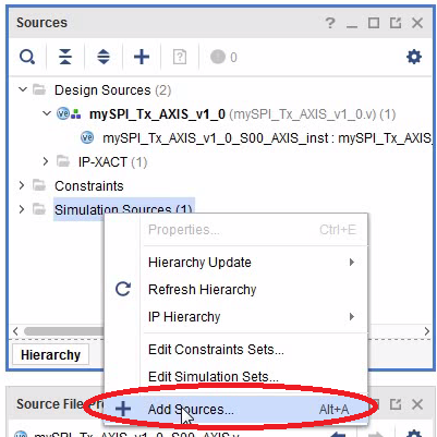
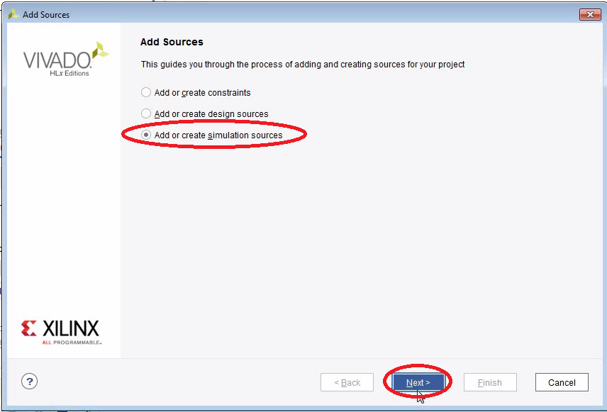
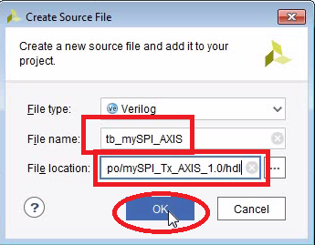
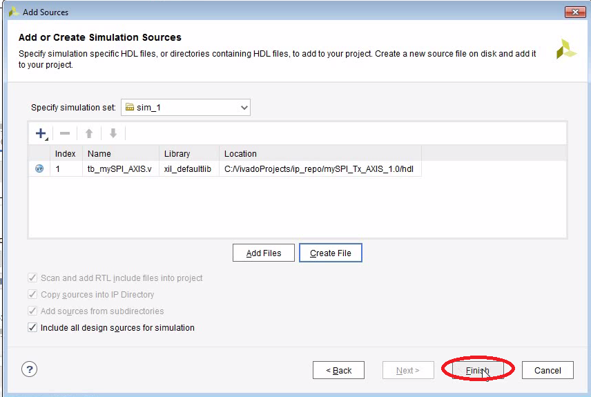
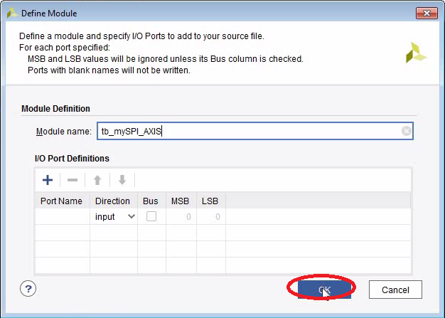
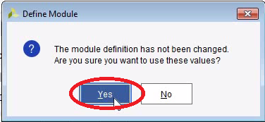
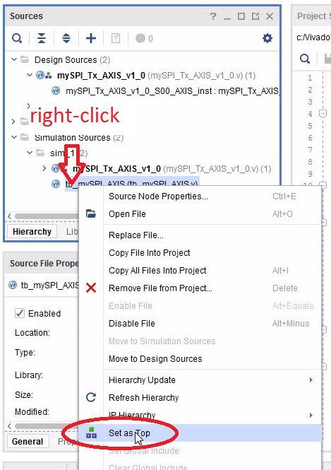
Add a Test Bench


Add the Test Bench Code
- Don’t forget to make the test bench file the top-level module

tb_mySPI_AXIS.v
`timescale 1ns / 1ps

module tb_mySPI_AXIS();
    wire sclk;
    wire mosi;
    wire ss;

    reg s00_axis_aclk = 0;
    reg s00_axis_aresetn = 0;
    wire s00_axis_tready;
    reg [31:0]s00_axis_tdata=0;
    reg s00_axis_tstrb=0;
    reg s00_axis_tlast=0;
    reg s00_axis_tvalid=0;

	mySPI_Tx_AXIS_v1_0_S00_AXIS # (
        .width(8),
        .clkdiv(2),
		.C_S_AXIS_TDATA_WIDTH(32)
	) mySPI_Tx_AXIS_v1_0_S00_AXIS_inst (
        .sclk(sclk),
        .mosi(mosi),
        .ss(ss),
		.S_AXIS_ACLK(s00_axis_aclk),
		.S_AXIS_ARESETN(s00_axis_aresetn),
		.S_AXIS_TREADY(s00_axis_tready),
		.S_AXIS_TDATA(s00_axis_tdata),
		.S_AXIS_TSTRB(s00_axis_tstrb),
		.S_AXIS_TLAST(s00_axis_tlast),
		.S_AXIS_TVALID(s00_axis_tvalid)
	);

    always begin
        #1 s00_axis_aclk=~s00_axis_aclk;
    end

    initial begin
        #20;
        @ (posedge s00_axis_aclk) s00_axis_tdata = 16'hAAAA;s00_axis_tvalid = 1;
        while (s00_axis_tready==0) begin
            @ (posedge s00_axis_aclk) ;
        end
        @ (posedge s00_axis_aclk) s00_axis_tdata = 16'h5555;s00_axis_tvalid = 1;
        while (s00_axis_tready==0) begin
            @ (posedge s00_axis_aclk) ;
        end
        @ (posedge s00_axis_aclk) s00_axis_tdata = 16'h0000;s00_axis_tvalid = 0;
    end
endmodule
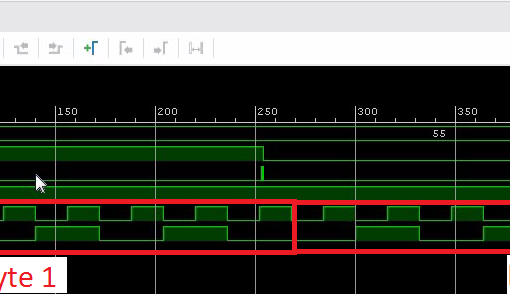
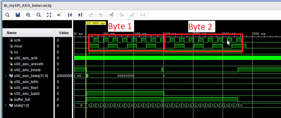
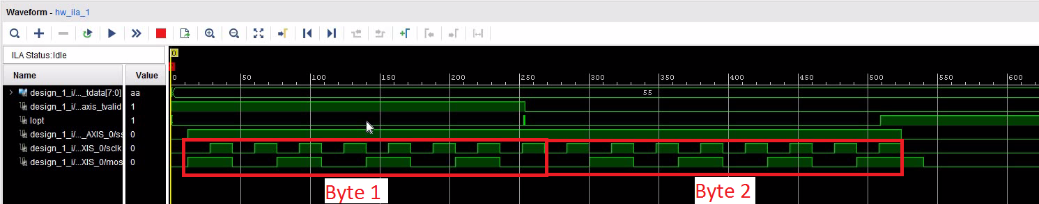
Simulate the SPI Transmitter
- Note that you can drag signals into the diagram. You need to reset the simulation and restart it (using the play-buttons on top of the screen). But you don’t need to run the behavioural simulation again unless you change the Veriolg code.
- To get more space it is useful to undock the diagram window.
- If you close the simulation you may be asked if you want to save the waveform configuration (a *.wcfg file). Make sure to save it to the project directory. You will be asked to add it to the project as well.


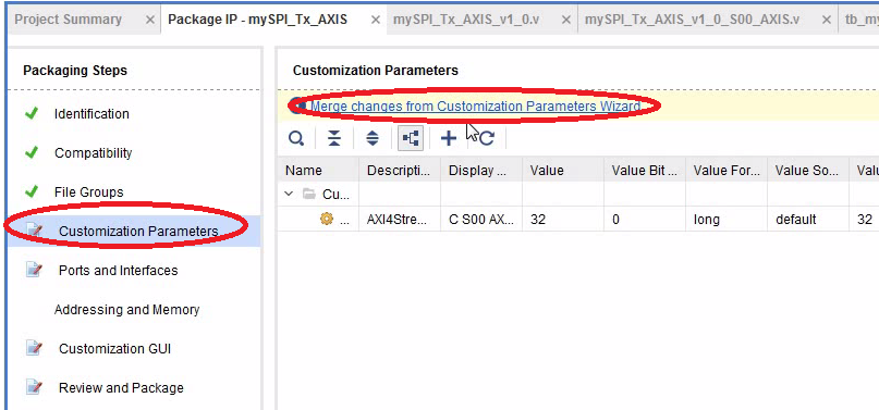
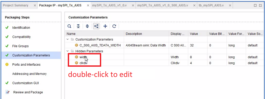
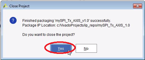
Package the IP Core


Next: Use the SPI Transmitter in a Block Diagram
- The IP Core should now be in c:/VivadoProjects/ip_repo/mySPI_Tx_AXIS_1.0
- You can close the Throw-Away project now and delete it.
- Click here to learn how to use your new IP core.