Every project starts with a blinking LED.
The Zynq FPGA family comes with an ARM processor (Xilinx calls it PS) and an FPGA fabric (referred to as PL). In order for something to run, we need to care about both sides. We have to create a “bitstream” which configures the PL side. If you come from the software developer side, think of it as your compiled binary. It is loaded into the static RAM of the FPGA and will be lost after you turn off the power. We also need to write a small C-program which runs on the PS side. This software initializes the FPGA and talks to the peripherals to make the LEDs blink. So, in this example, the ARM processor will do the heavy lifting to flash the LEDs.
Generally, the development workflow looks like this:
- Write FPGA code (this may include block designs, VHDL or Verilog code, creating your own modules/IP cores).
- Run Synthesis and Implementation to generate the bitstream.
- Use the SDK to write and compile your C/C++ code into an ELF file.
- Use the SDK to upload the bitstream and the ELF file into the Zedboard.
- Optional: If everything works, you can create a boot loader and put everything onto an SD-card, so your software/bitstream is loaded automatically when the board is powered up.
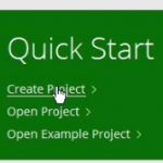
Let’s Create a New Project
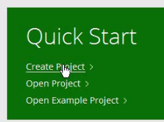
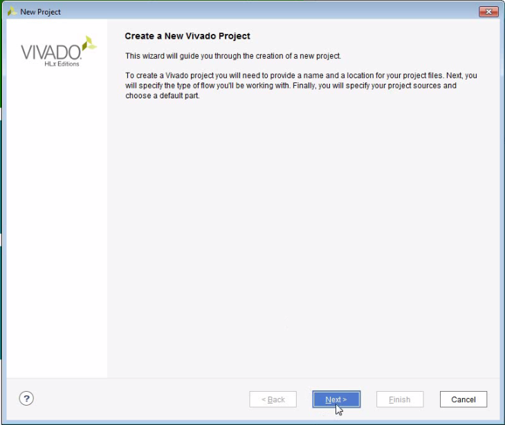
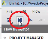
- Open Vivado
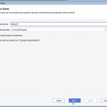
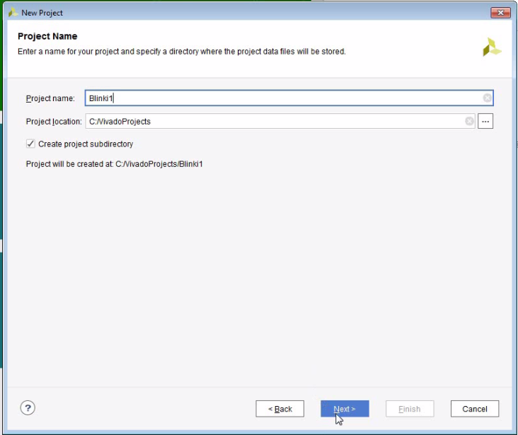
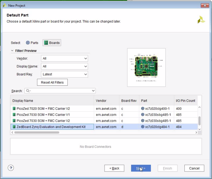
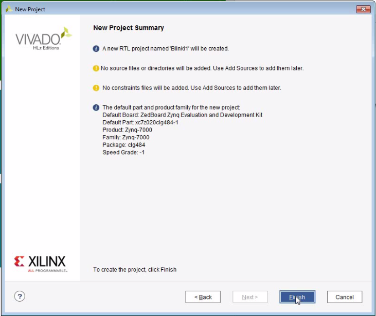
- Create a project named “Blinki1”

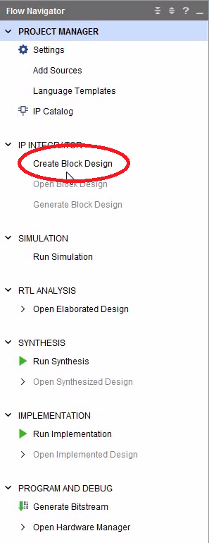
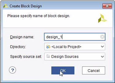
Create a Block Design
- A block-design is often the top-level FPGA code. It can be used to wire up the different logic modules (aka IP cores).
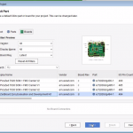
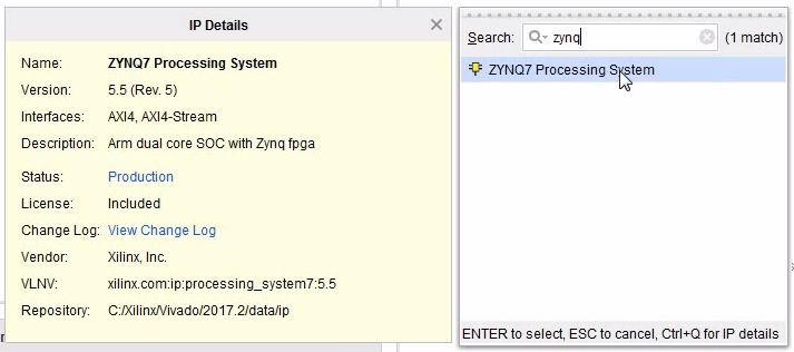
- A block design always contains the ZYNQ7 Processing System.
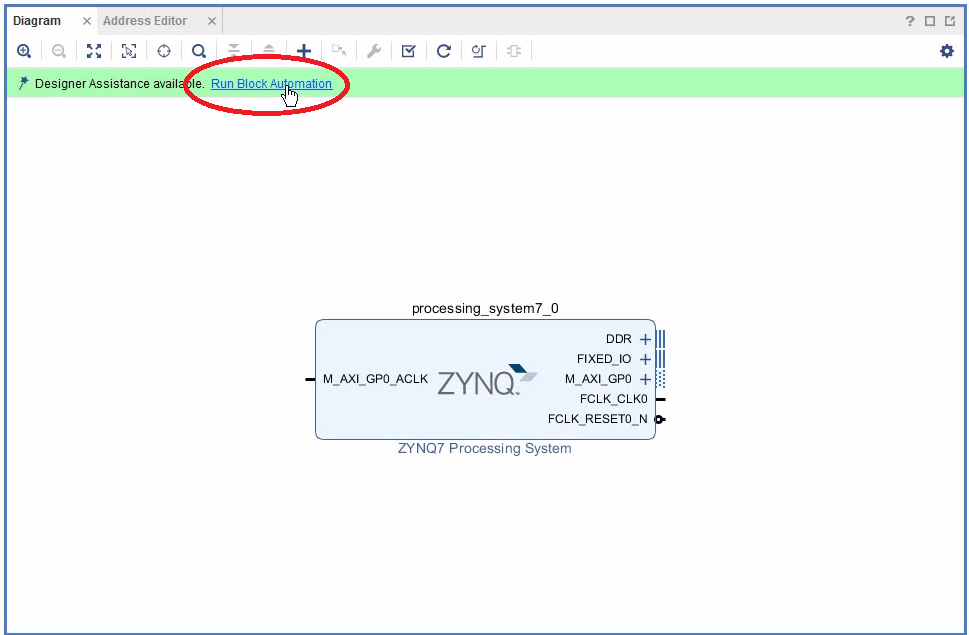
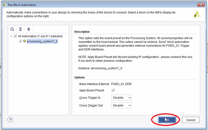
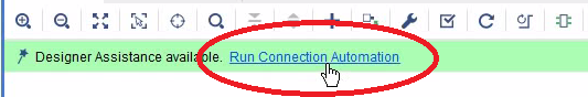
- Block Automation tries to guess what you want to do. Very useful, however not always correct.
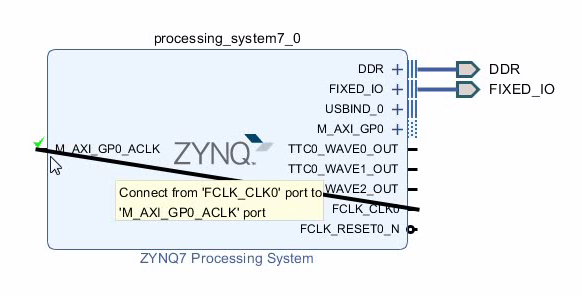
- You always need to connect the clock output FCLK_CLK0 to the AXI bus M_AXI_GP0_ACLK.


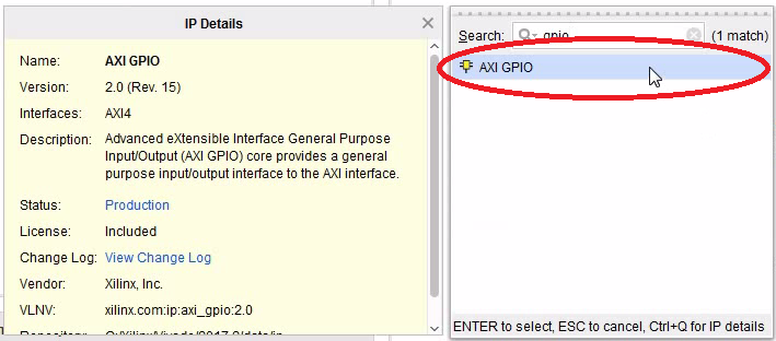
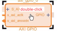
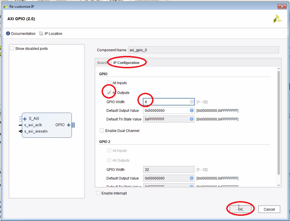
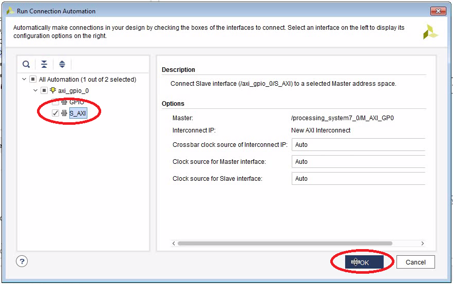
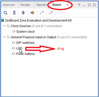
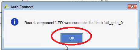
Add a General Purpose Output Port
- We are going to use an 8-bit General Purpose Output Port to drive the LEDs.
- This port is connected to the AXI bus.
- The AXI bus is the ultimate interface to connect your logic to the CPU.


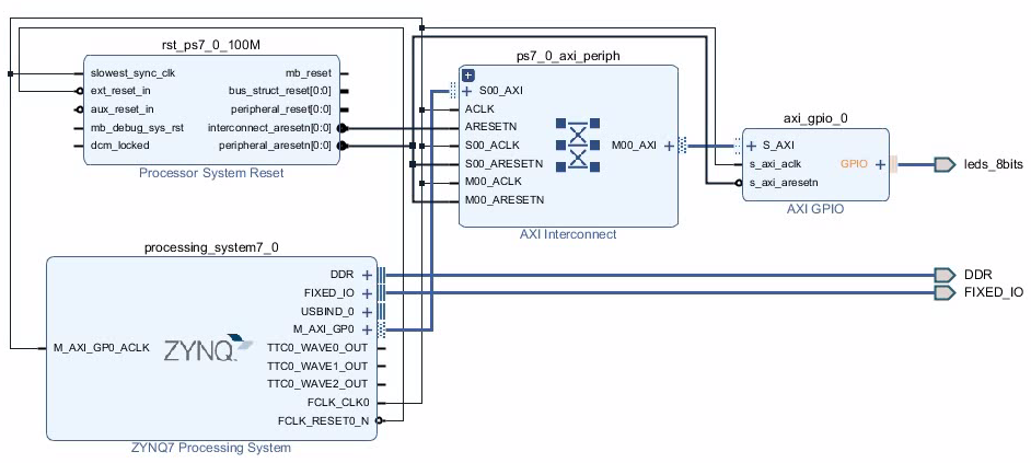
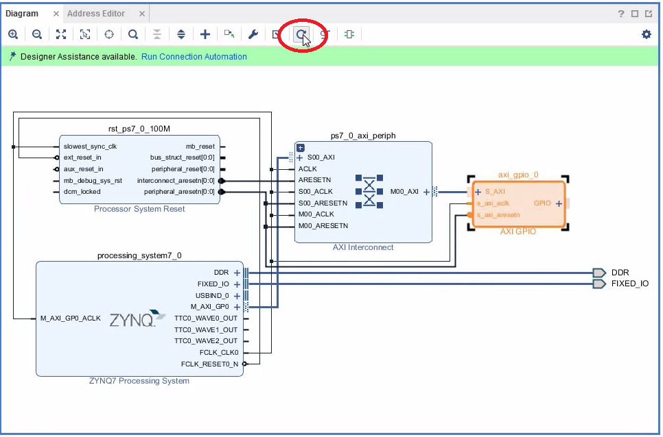
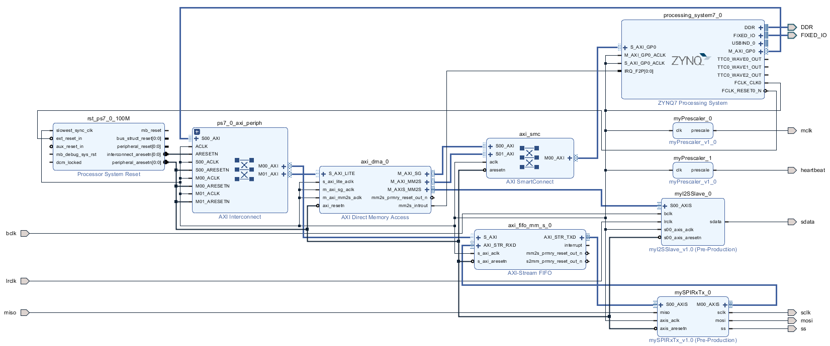
View the Complete Block Design
This is how your block design should look like:
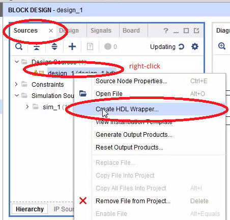
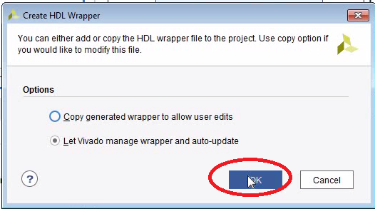
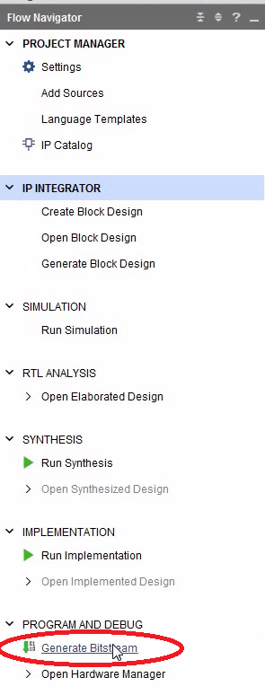
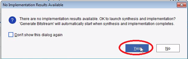
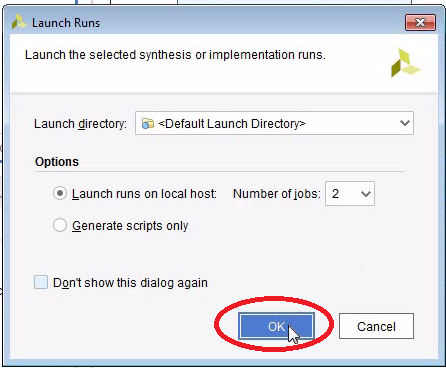
Create the Bitstream
- We need to put an HDL Wrapper around the block design. HDL means “Hardware Definition Language”. Verilog and VHDL seem to be the most common languages. I prefer Verilog. The HDL wrapper is basically some code which invokes the block diagram and provides and interface to the calling HDL module. Just remember, in order to use a block diagram you need an HDL wrapper.
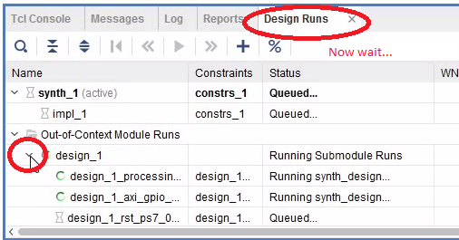
- Be aware that the synthesis and the implementation will take a few minutes to run.


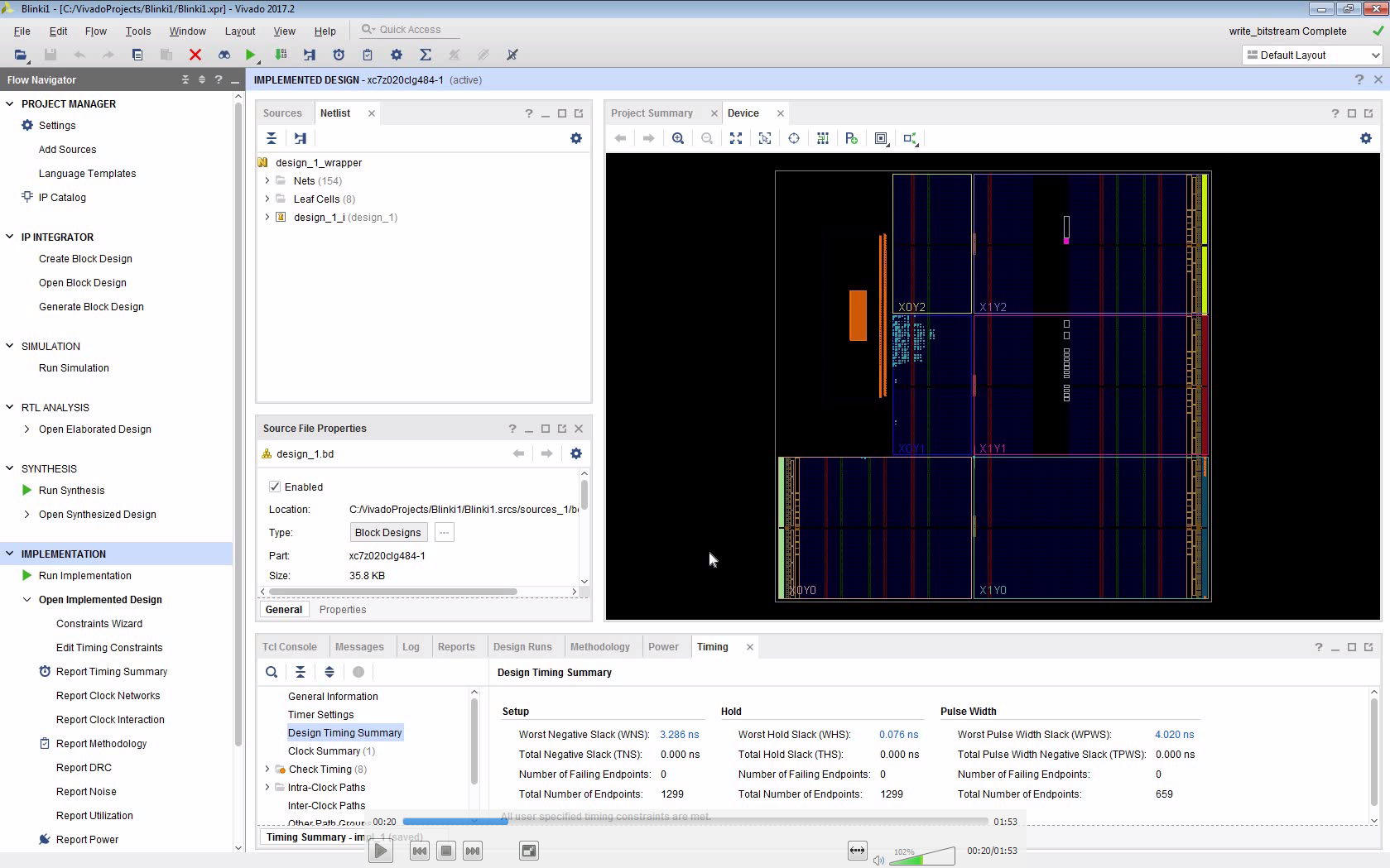
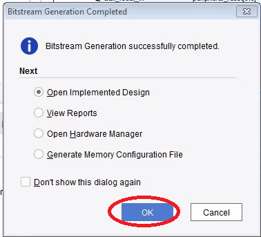
Open the Implemented Design
- If you clicked “OK” in the last dialogue, the implemented design is opened.
- For the next step it seems to be important that you have opened the implemented design.
This is how the implemented design looks like:
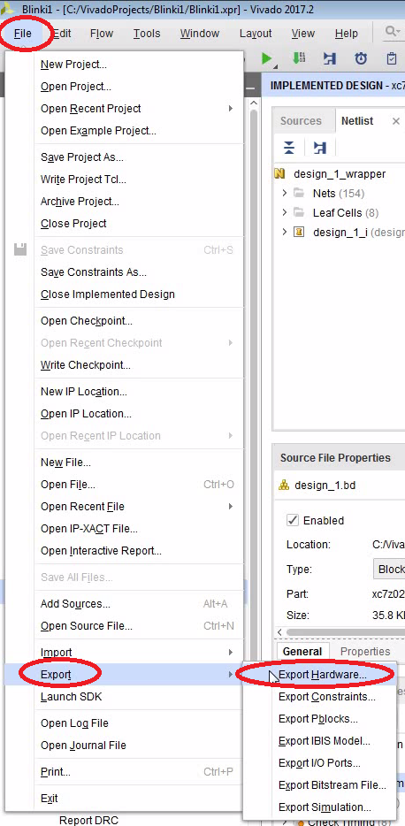
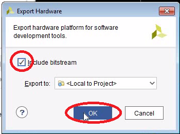
Export the Hardware to the SDK
- We need to write the C-code using the Xilinx Software Development Kit (SDK or sometimes XSDK).
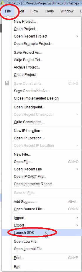
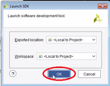
- In order to do that, let’s export the hardware and then open the SDK.


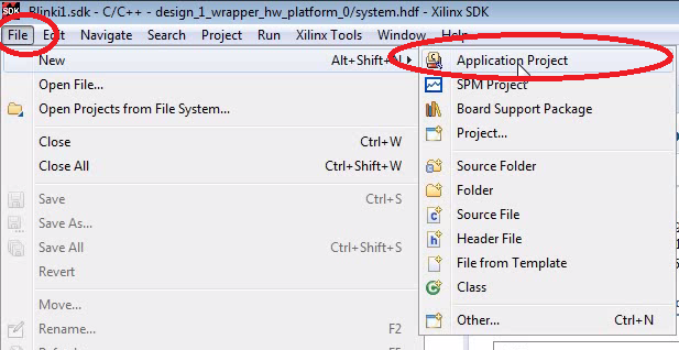
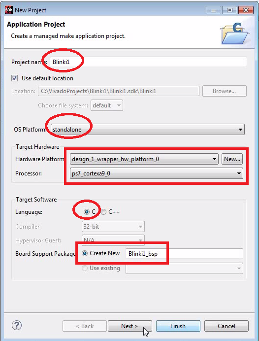
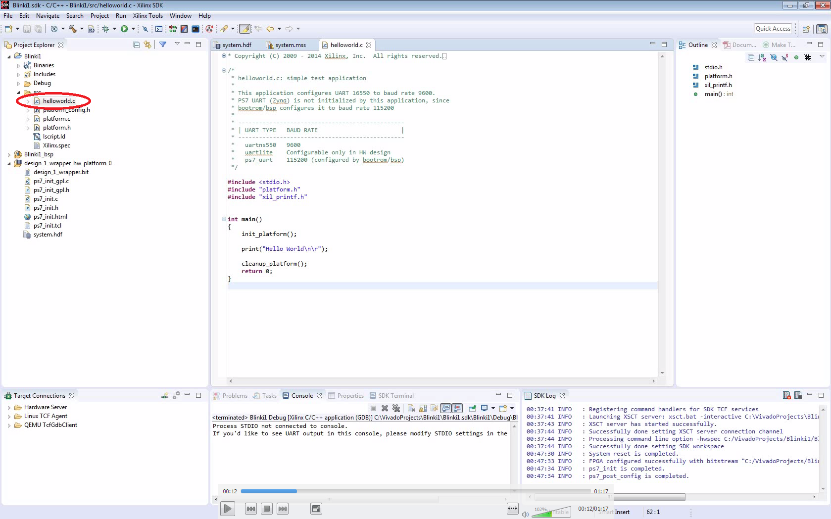
Create Standalone Project in the SDK
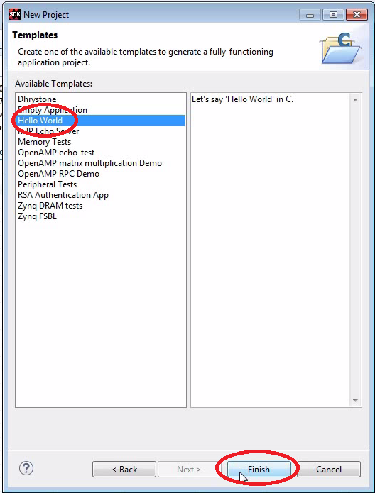
- We create a standalone C project using the “Hello World” template.
- After that there are 3 projects:
- The main project “Blinki1”
- The board support project “Blinki1_bsp”
- The design wrapper “design_1_wrapper_hw_platform_0”
- The project is already compiling and should finish without errors.


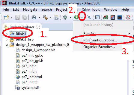
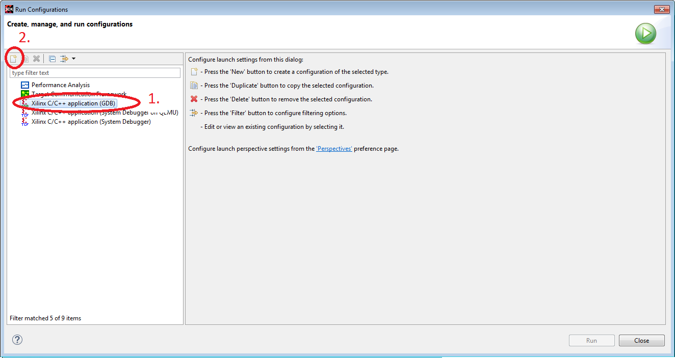
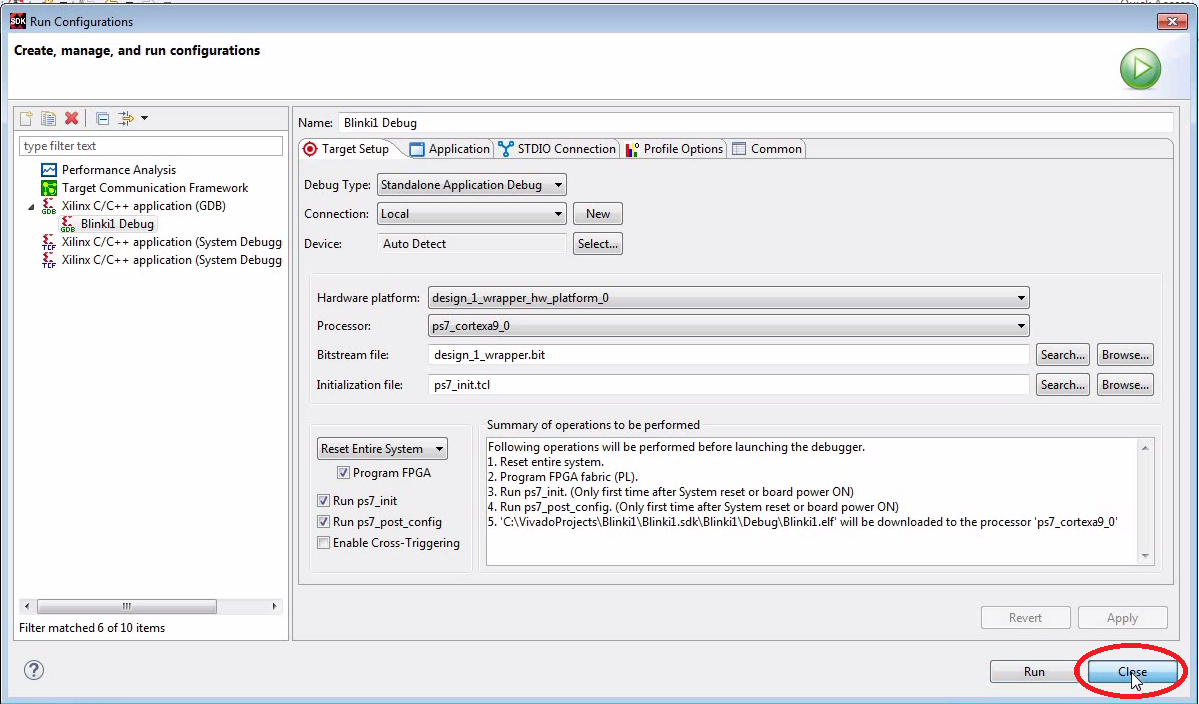
Create Run Configuration
- We use GDB to run the code.
- Don’t forget to select the main project before you click on “Run Configurations”. A lot of fields will not be populated with the appropriate defaults otherwise.


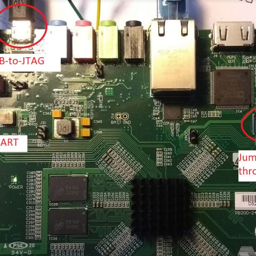
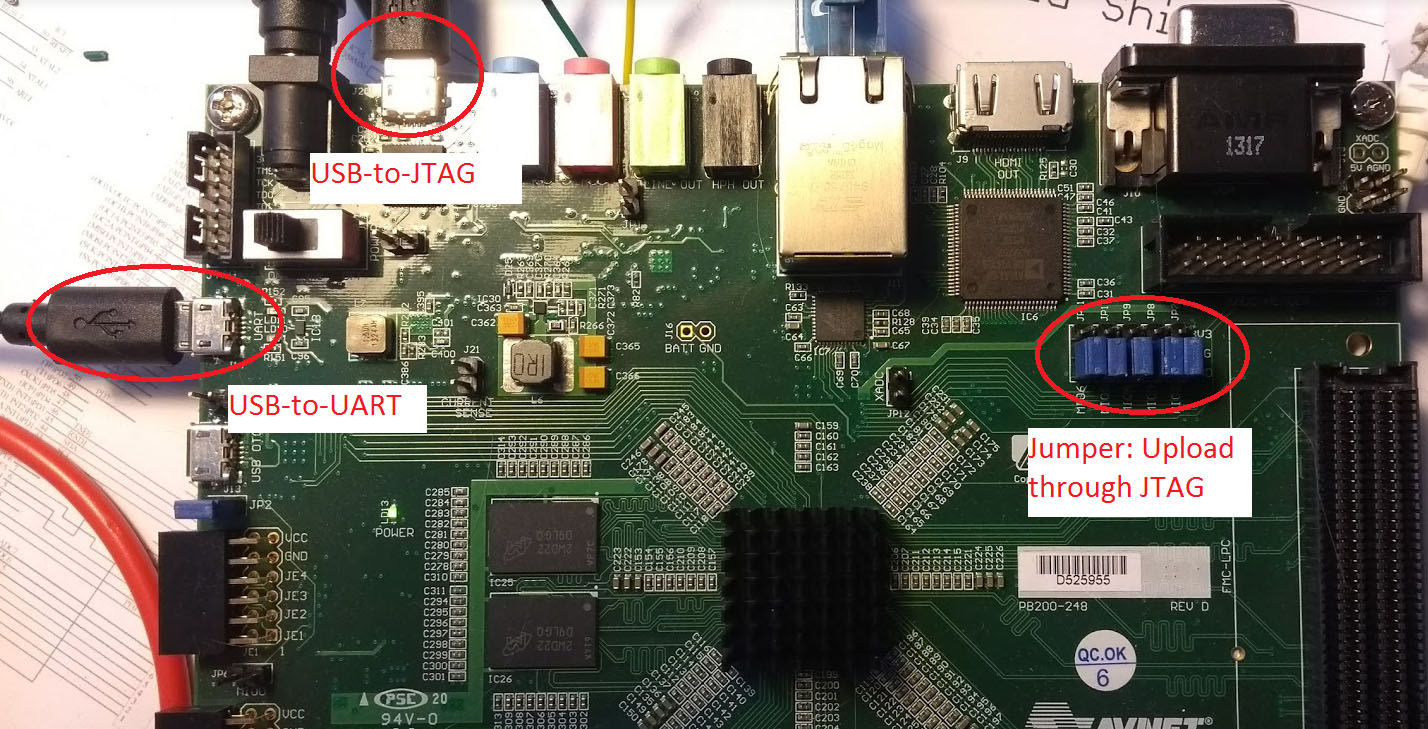
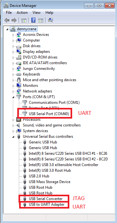
Connect Hardware
This is just a quick summary. I assume all the drivers have already been correctly installed.
- We upload the code through the on-board JTAG adapter (which us connected by a USB cable)
- We communicate though a UART (which is connected by another USB cable)
- Make sure the jumpers are set correctly on the Zedboard
- Turn on the power (really!).


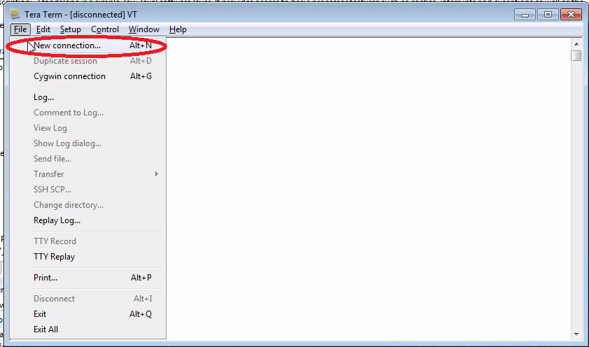
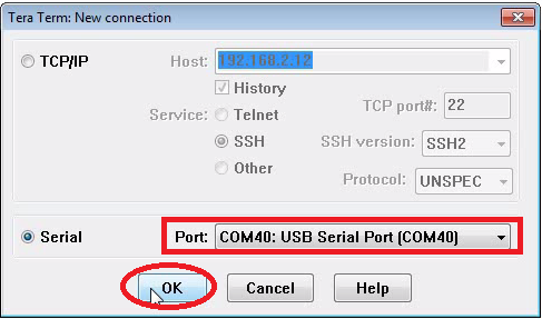
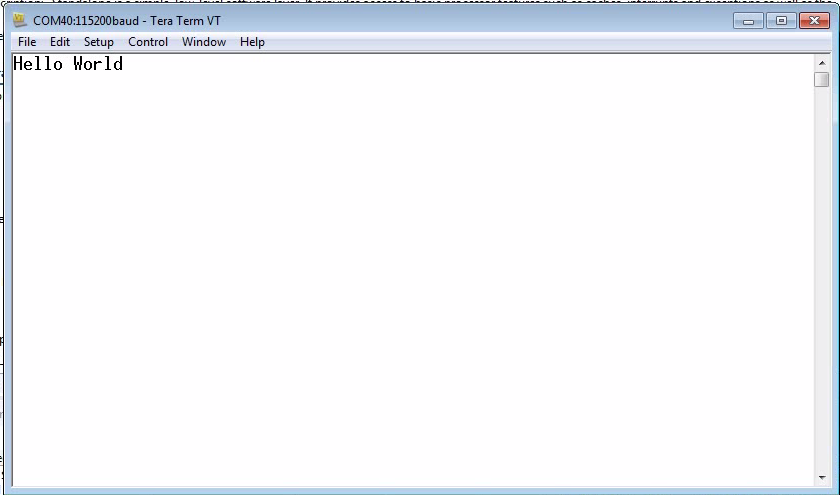
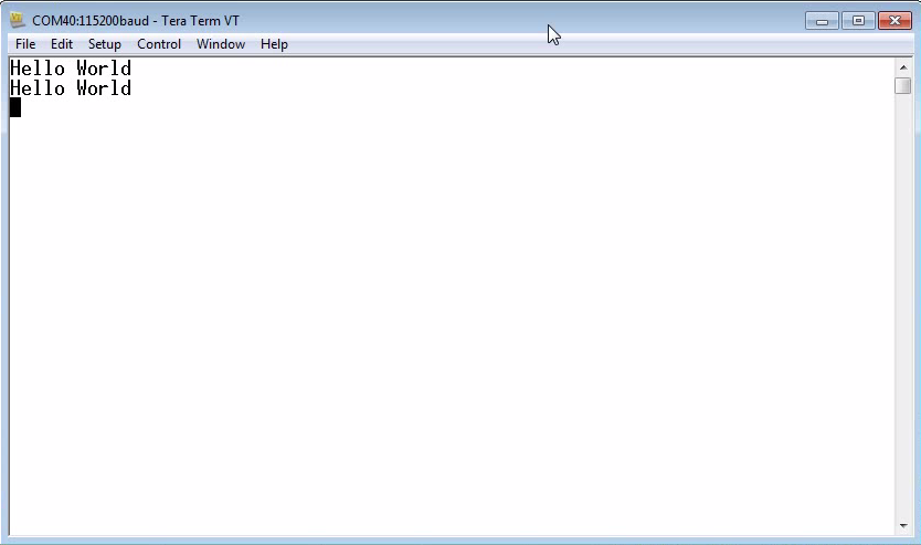
Setup Tera Term
- I really like Tera Term as a serial terminal.
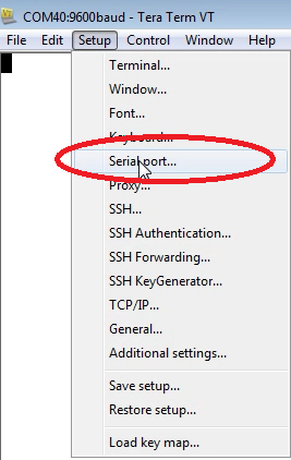
- Connect to the virtual COM port using 115200 baud, 8N1 (8 data bits, no parity, 1 stop bit)


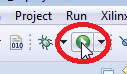
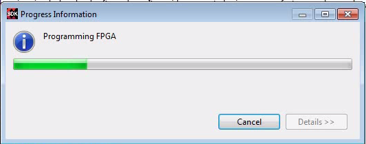
Run the Program
- The bitstream as well as the compiled C-program will be uploaded.
- You should see “Hello World” in the terminal.


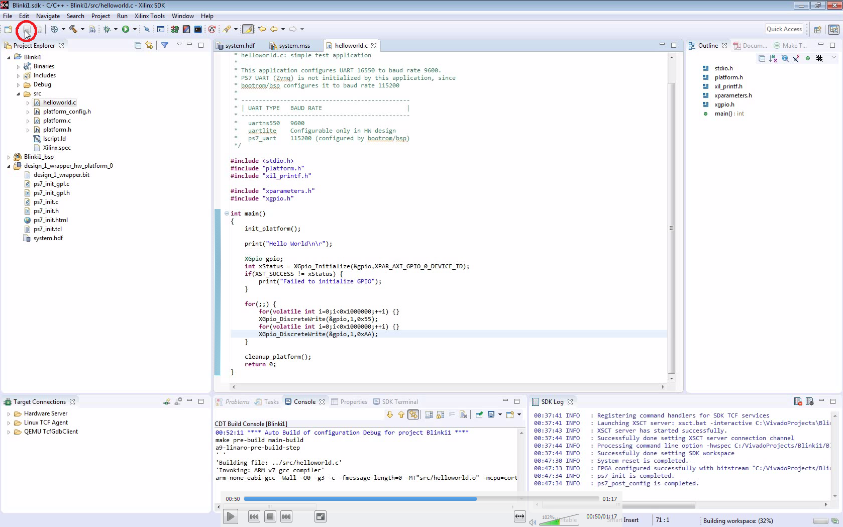
Add the Blinki Code
- Open helloworld.c
- Add the source code which lets the LEDs blink.
- The code will be compiled when you save the file.
- Run the compiled code.


#include <stdio.h>
#include "platform.h"
#include "xil_printf.h"

#include "xparameters.h"
#include "xgpio.h"

int main()
{
    init_platform();

    print("Hello World\r\n");

    XGpio gpio;
    int xStatus = XGpio_Initialize(&gpio,XPAR_AXI_GPIO_0_DEVICE_ID);
    if(XST_SUCCESS != xStatus) {
        print("Failed to initialize GPIO");
    }

    for(;;) {
        for(volatile int i=0;i<0x1000000;++i) {}
        XGpio_DiscreteWrite(&gpio,1,0x55);
        for(volatile int i=0;i<span data-mce-type="bookmark" style="display: inline-block; width: 0px; overflow: hidden; line-height: 0;" class="mce_SELRES_start"></span><0x1000000;++i) {}
        XGpio_DiscreteWrite(&gpio,1,0xAA);
    }

    cleanup_platform();
    return 0;
}
Continue Reading
Continue here to let the PL side do the blinking.
