In the previous post we learned how to create an SPI transmitter with an AXI Stream interface. Now let’s use it in a block diagram. And write some C-Code to drive it. We will not hook up real hardware to the SPI as this is just for demonstration.
In this tutorial we will learn
- How to connect an AXI Stream Slave to the ZYNQ using a stock AXI FIFO IP Core.
- How to talk to the FIFO using stand-alone C-code.
- How to add Debug cores to your FPGA so you can use Vivado’s built-in logic-analyzer.
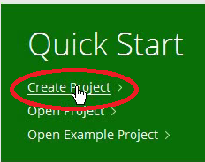
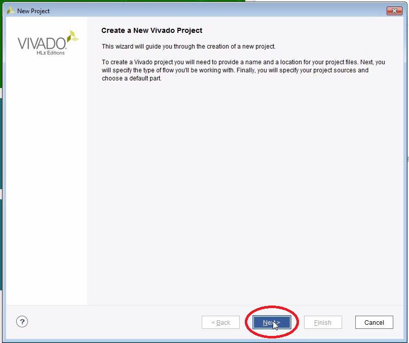
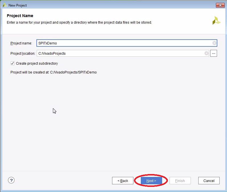
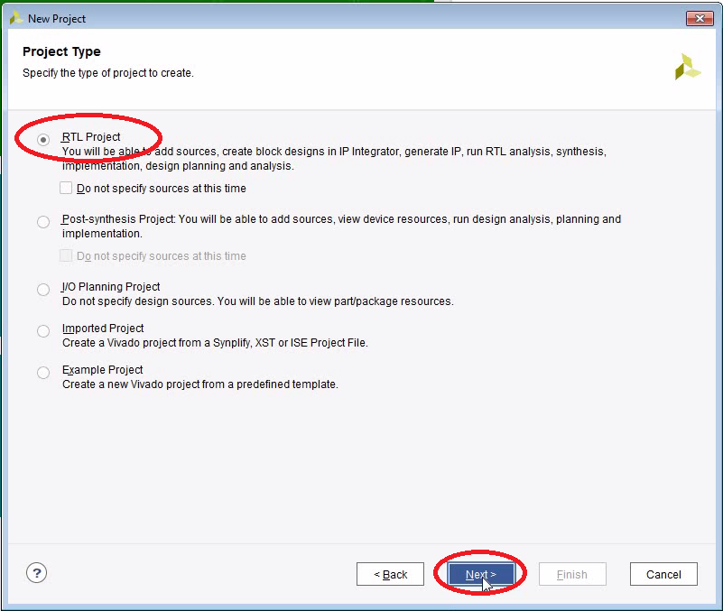
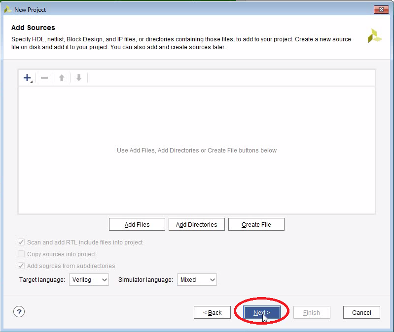
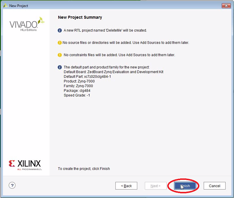
Create a New Project


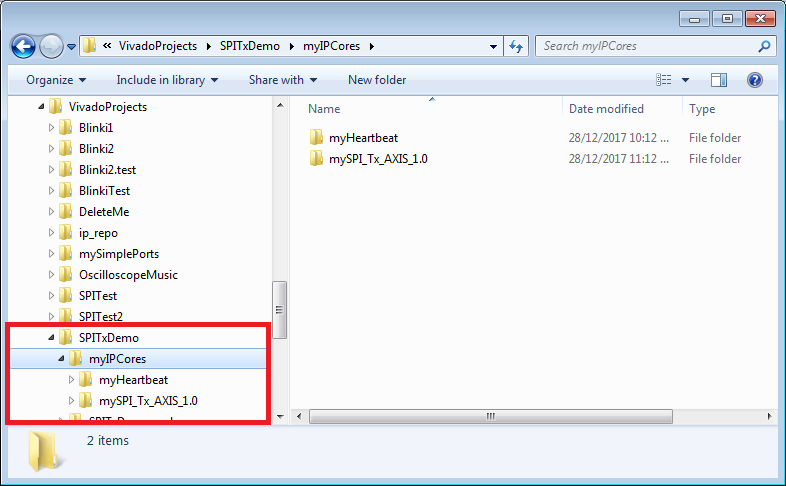
Copy the two IP Cores into the Project
- We just created a new project in c:/VivadoProjects/SPITxDemo. Create a sub-directory named myIPCores in the new project directory
- Unzip these two IP Cores into myIPCores:

We made the Heartbeat IP core here:
ZYNQ: Blinki (Now the FPGA does the blinking)
We made the SPI Transmitter here:
ZYNQ: SPI Transmitter Using an AXI Stream Interface - Why I am not using a global repository? See here.

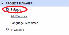
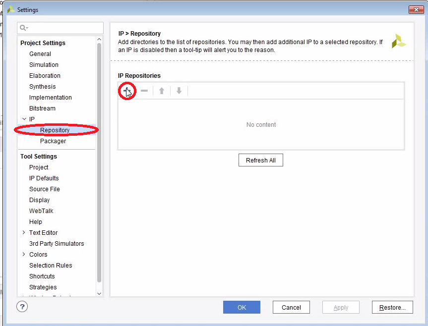
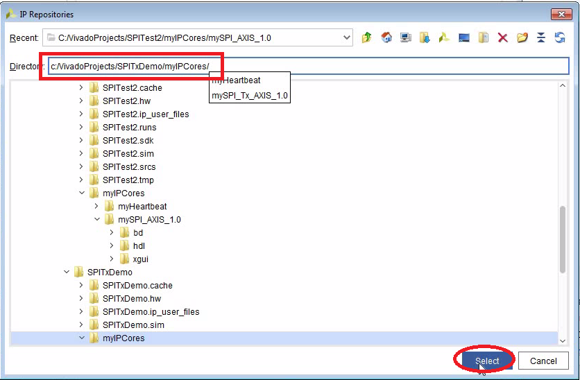
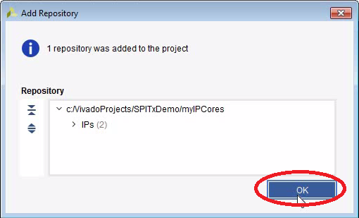
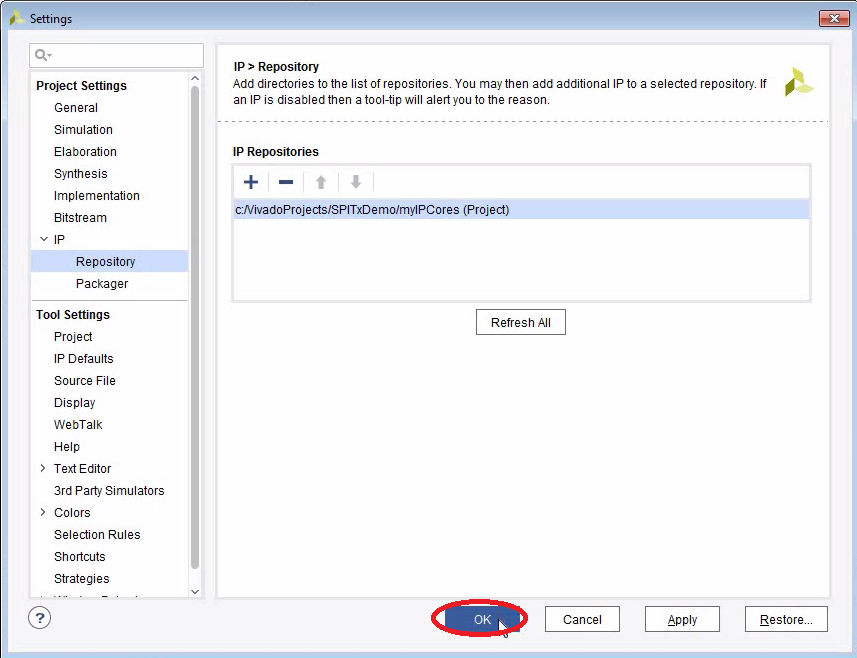
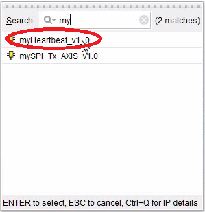
Add myIPCores to Project


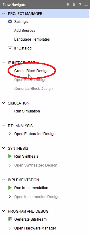
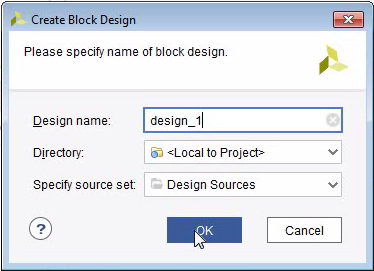
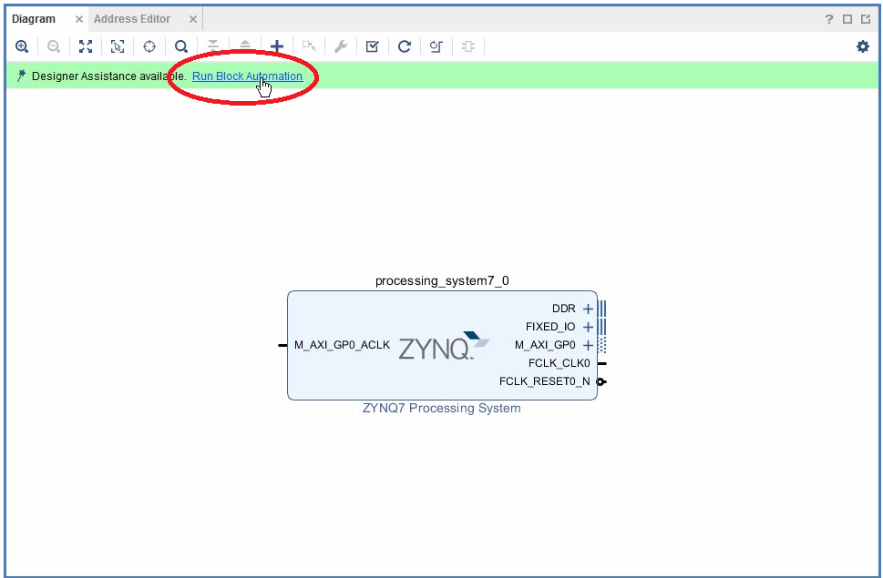
Create a Block Design and add the ZYNQ PS
- A block-design is often the top-level FPGA code. It can be used to wire up the different logic modules (aka IP cores).
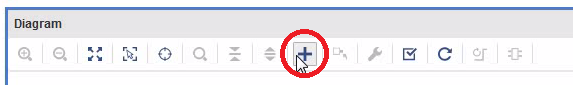
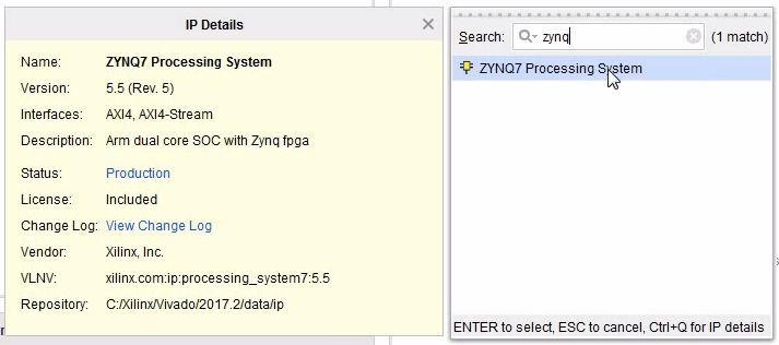
- A block design always contains the ZYNQ7 Processing System.
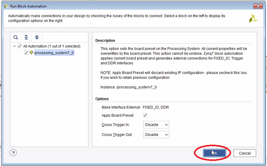
- Block Automation tries to guess what you want to do. Very useful, however not always correct.
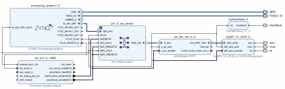
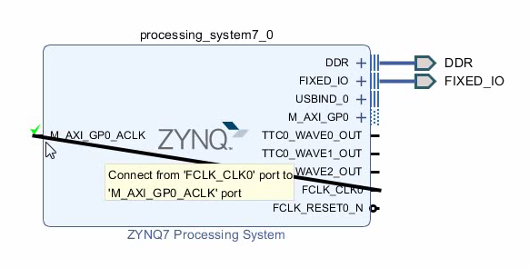
- You always need to connect the clock output FCLK_CLK0 to the AXI bus M_AXI_GP0_ACLK.


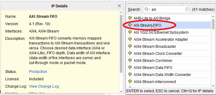
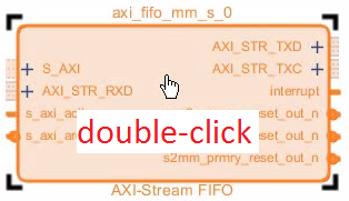
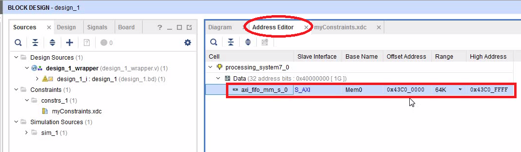
Add an AXI Stream FIFO to the Block Diagram
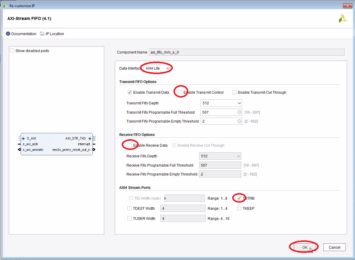
- This FIFO is the interface between the SPI Transmitter and the ARM processor. It will provide a memory-mapped interface which we can talk to using the C-code.
- We are not really using the STRB feature. But there will be warnings if we don’t connect it.


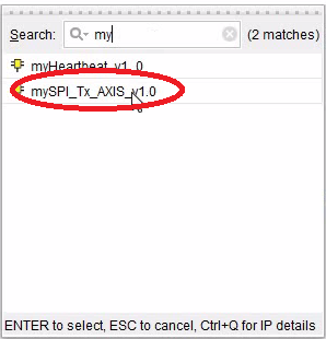
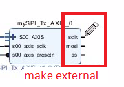
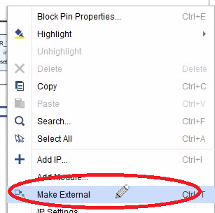
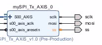
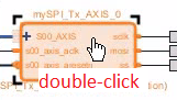
Add the SPI Transmitter
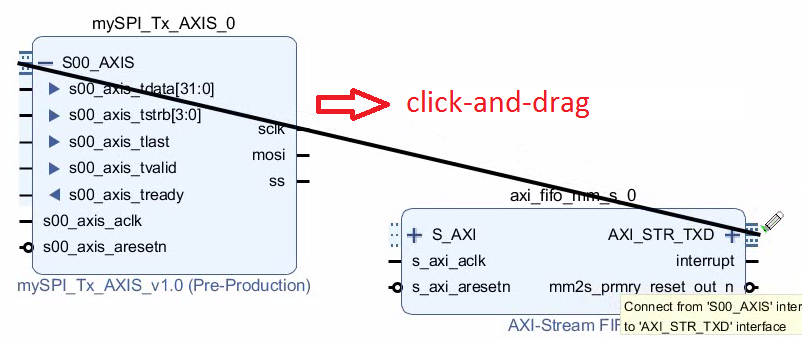
- Connect the FIFO TXD interface to the SPI Transmitter AXI Stream Slave interface.


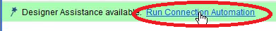
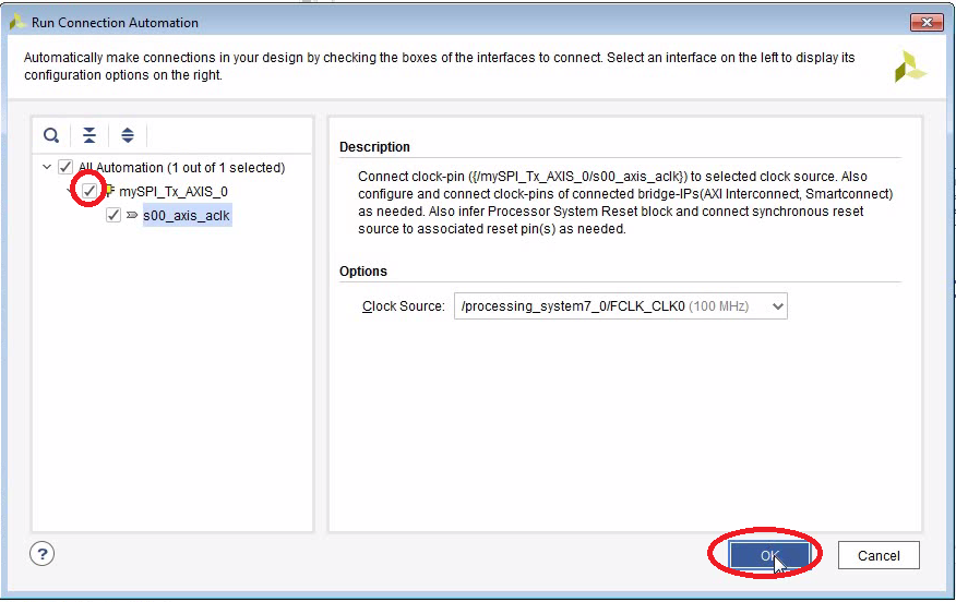
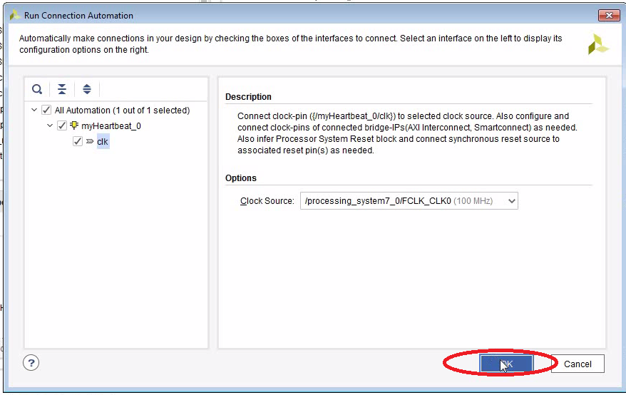
Run Connection Automation


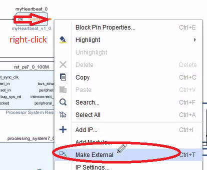
Add the Heartbeat LED


The Full Block Diagram
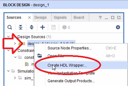
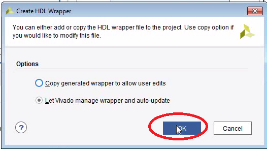
Create HDL Wrapper
- Not sure why we get the warnings. Seems to be a known issue.


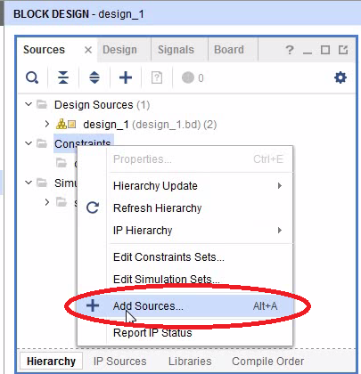
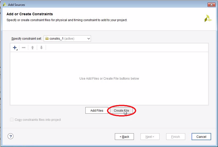
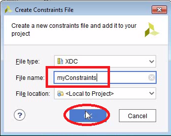
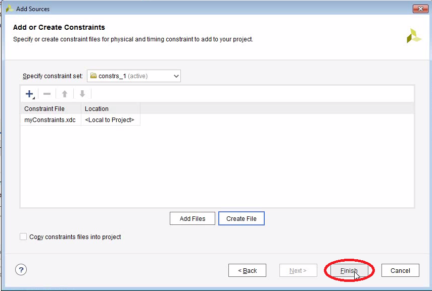
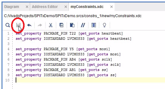
Add a Constraints File
- Pin definitions are normally kept in a so-called Constraints-File.


Setup the Pins
- You will have to look up in the schematics which pin the LED is connected to.
- You also need to define the logic levels.
- We are connecting the SPI pins to the audio codec although we are not going to talk to it, yet.

set_property PACKAGE_PIN T22 [get_ports heartbeat]
set_property IOSTANDARD LVCMOS33 [get_ports heartbeat]

set_property PACKAGE_PIN Y5 [get_ports mosi]
set_property IOSTANDARD LVCMOS33 [get_ports mosi]
set_property PACKAGE_PIN AB4 [get_ports sclk]
set_property IOSTANDARD LVCMOS33 [get_ports sclk]
set_property PACKAGE_PIN AB1 [get_ports ss]
set_property IOSTANDARD LVCMOS33 [get_ports ss]
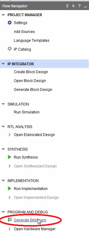
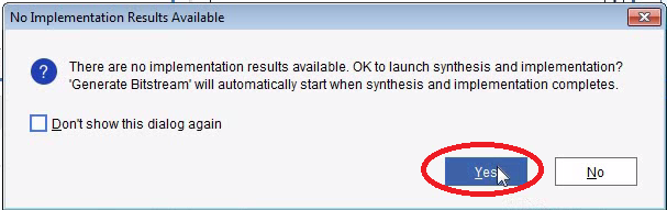
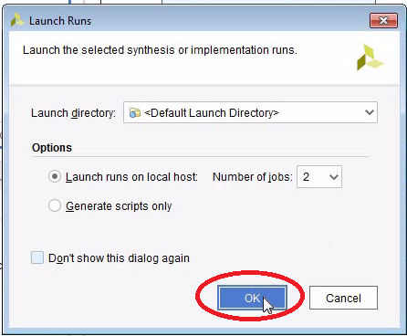
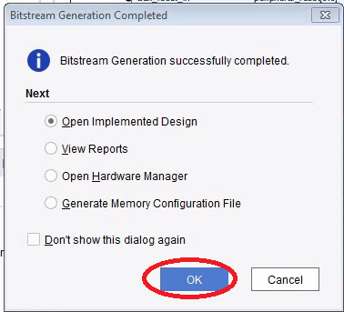
Create the Bitstream
- Be aware that the synthesis and the implementation will take a few minutes to run.
- After the bitstream has been created, we open the Implemented Design.
- For the next step it seems to be important that you have opened the implemented design.


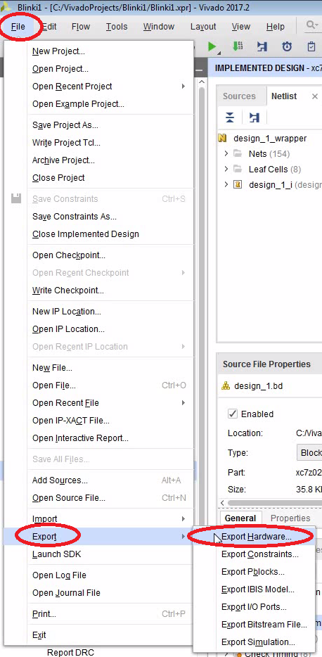
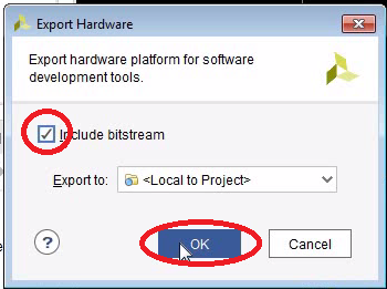
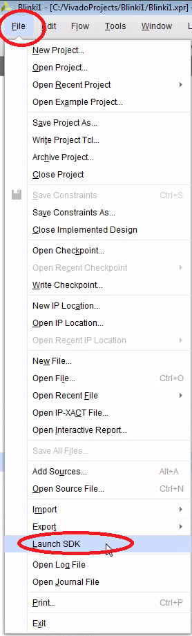
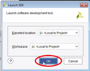
Export the Hardware to the SDK
- We need to write the C-code using the Xilinx Software Development Kit (SDK or sometimes XSDK).
- In order to do that, let’s export the hardware and then open the SDK.


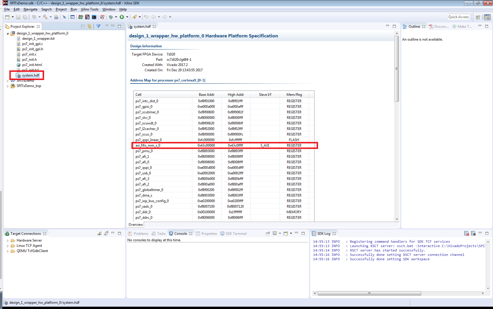
Have a Look Around


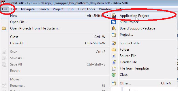
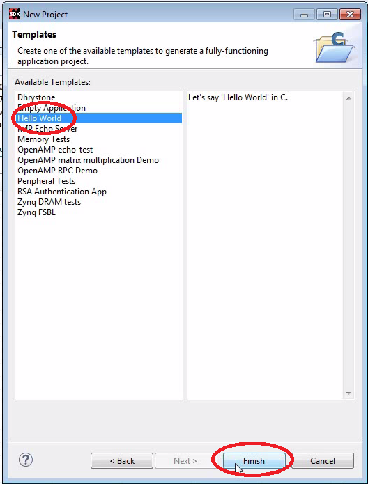
Create Standalone Project in the SDK
- We create a standalone C project using the “Hello World” template.
- After that there are 3 projects:
- The main project “SPITxDemo”
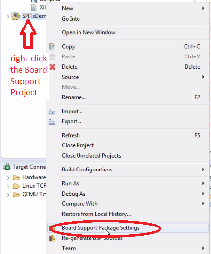
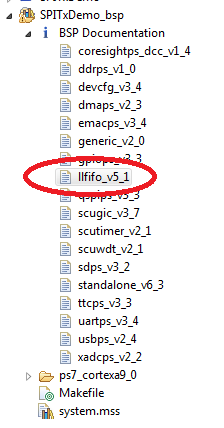
- The board support project “SPITxDemo_bsp”
- The design wrapper “design_1_wrapper_hw_platform_0”
- The project is already compiling and should finish without errors.


Have a Look Around


Add the C-Code
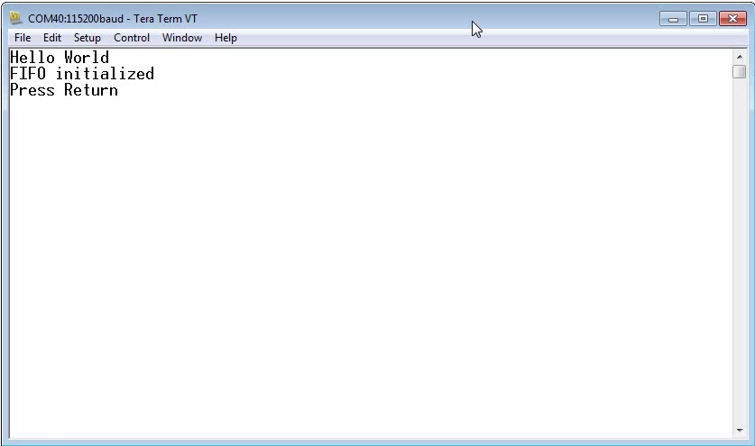
- This code waits until the user presses RETURN.
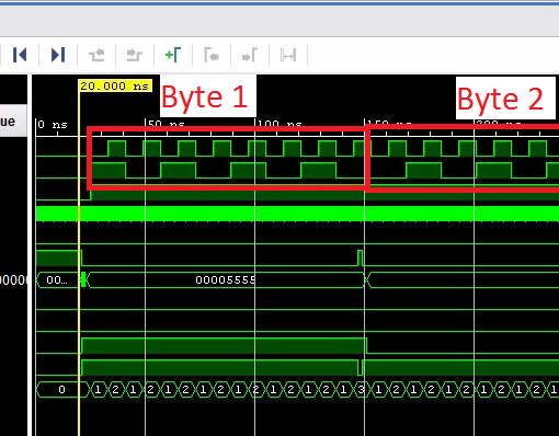
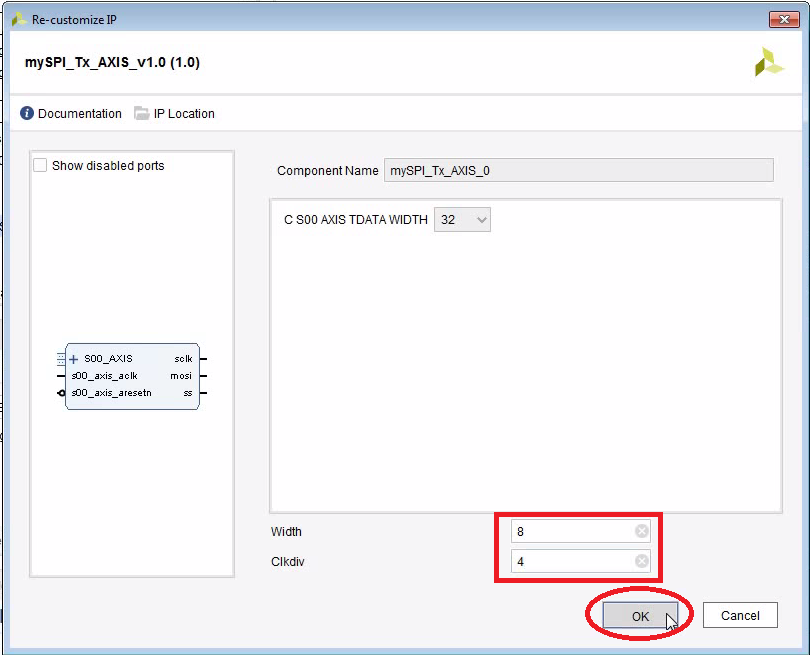
- Then it puts 0xAAAAAAAA and 0x55555555 into the FIFO. Note that we configured the SPI interface to be 8 bits wide. So only the lower 8 bits are actually used.

#include <stdio.h>
#include "platform.h"
#include "xil_printf.h"
#include "xil_types.h"
#include "xstatus.h"
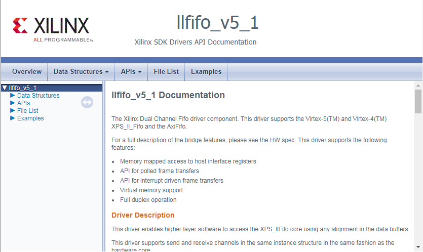
#include "xllfifo.h"
#include "xparameters.h"
#define WORD_SIZE 4 // Size of words in bytes
#define MAX_PACKET_LEN 4
#define NO_OF_PACKETS 64
#define MAX_DATA_BUFFER_SIZE NO_OF_PACKETS*MAX_PACKET_LEN
int main()
{
init_platform();
print("Hello Worldnr");
XLlFifo fifo;
int xStatus = XLlFifo_CfgInitialize(&fifo,XLlFfio_LookupConfig(XPAR_AXI_FIFO_MM_S_0_DEVICE_ID),(UINTPTR)XPAR_AXI_FIFO_MM_S_0_BASEADDR);
if(XST_SUCCESS != xStatus) {
print("Failed to initialize FIFOnr");
}
print("FIFO initializednr");
// Check for the Reset value
int Status = XLlFifo_Status(&fifo);
XLlFifo_IntClear(&fifo,0xffffffff);
Status = XLlFifo_Status(&fifo);
if(Status != 0x0) {
print("Reset value wrongnr");
}
for(;;)
{
print("Press Returnnr");
getchar();
print("Sendingnr");
XLlFifo_TxPutWord(&fifo, 0xAAAAAAAA);
XLlFifo_TxPutWord(&fifo, 0x55555555);
XLlFifo_iTxSetLen(&fifo, 2 * WORD_SIZE);
}
print("Good byenr");
cleanup_platform();
return 0;
}
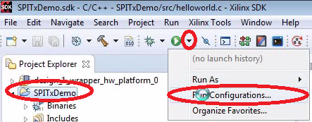
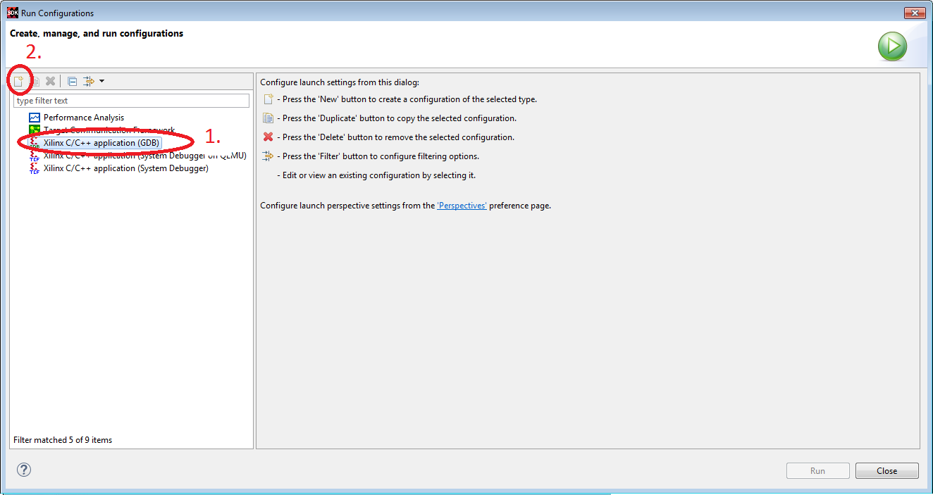
Create Run Configuration
- We use GDB to run the code.
- Don’t forget to select the main project before you click on “Run Configurations”. A lot of fields will not be populated with the appropriate defaults otherwise.


Connect Hardware and run Tera Term
- Refer to here on how to setup the jumpers and how to run Tera Term.
- Hint: If the board has been programmed with an old design, you may have to power-cycle the Zedboard. Otherwise you will get an unspecific error message.
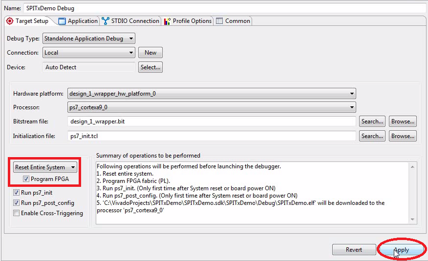
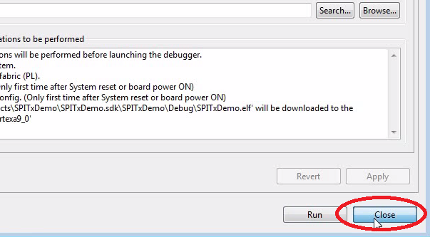
Run the Program
- The bitstream as well as the compiled C-program will be uploaded.
- You should see “Hello World” in the terminal.


Download the Complete Project
- To upload the software to the Zedboard, open the project in Vivado, then click on “Launch SDK”.
- There seems to be a bug when updating the SDK project which selects a wrong UART driver (refer to “SDK Auto Update Bug” to fix it).
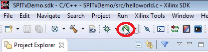
- Select the project SPITxDemo and click “Run” (the “play” button at the top of the window).
Next: Probe the SPI with Debug Cores
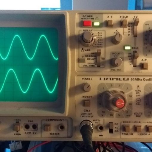
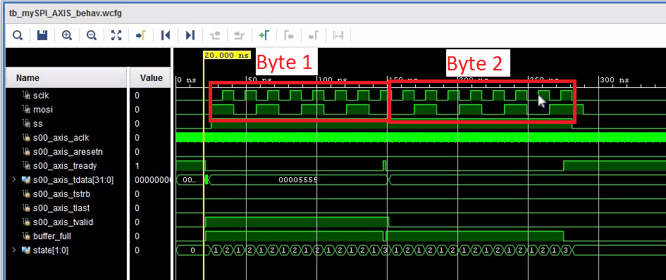
- If you would probe with an Oscilloscope on pins 1, 3 and 5 of JB1, you could see the 16 clock cycles and the bits shifted out whenever you press RETURN in the terminal.
- Vivado comes with a built-in logic tester. The next tutorial shows you how to probe the SPI signals using the Debug Cores which you can put into the FPGA.
- Click here to learn how to use Debug Cores.
