In this tutorial we add an I2S transmitter to the design. This enables us to finally generate an audio signal. This tutorial is based on the last post where we already configured the codec.
In this tutorial we will learn
- How to create an I2S interface with a slave AXI stream interface.
- We are writing a simple C-program which sends a sine wave to the codec (sounds actually quite annoying after a while…).
The I2S Interface of the ADAU1761
This is the basic timing timing of the I2S mode we want to use (refer to the ADAU1761 datasheet):
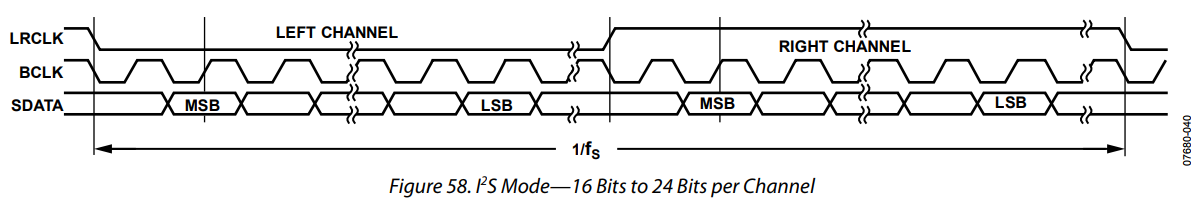
- We are going to use a 32-bit Slave AXI Stream Interface.
- The upper 16 bits will contain the left channel, the lower 16 bits will contain the right channel.
- If we keep providing data, we will get a continuous clock signal on BCLK with a 50% duty cycle. BCLK will run at 2.5MHz. Data is accepted at the rising edge of BCLK.
- Each frame starts with the low-transition of LRCLK.
- There are 32 clock cycles of BCLK in each channel. That means, we have to pad unused bits with 0. The data is left-aligned and starts with the MSB.
- The I2S format apparently ignores the first bit.
- 32 clock cycles at 2 channels and 2.5MHz clock rate equates to 39.0625 kHz sampling rate.
- In this example mclk is 4x faster than BCLK, i.e. 10MHz.
The IP-Core we are Using

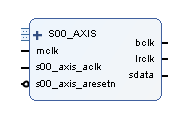
The I2S IP-Core
This is how the I2S controller looks like:
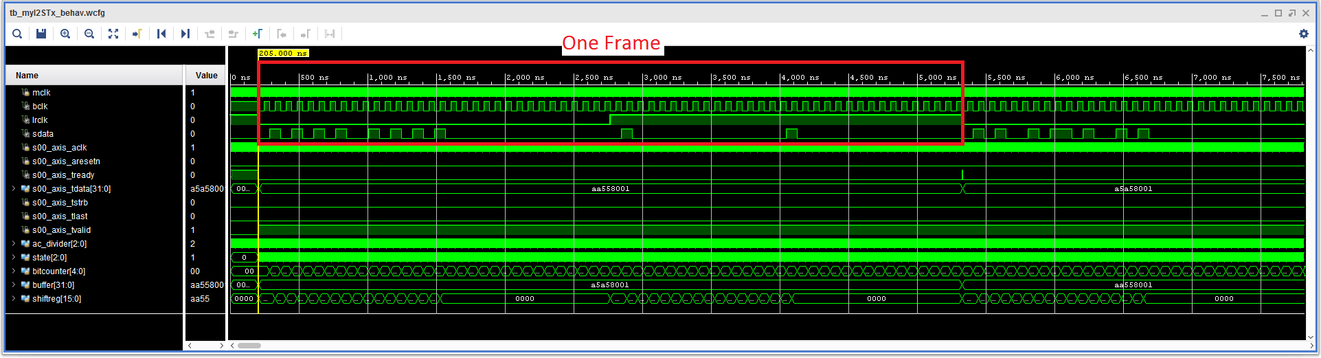
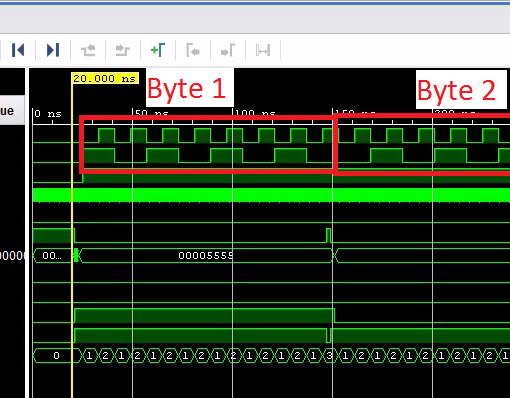
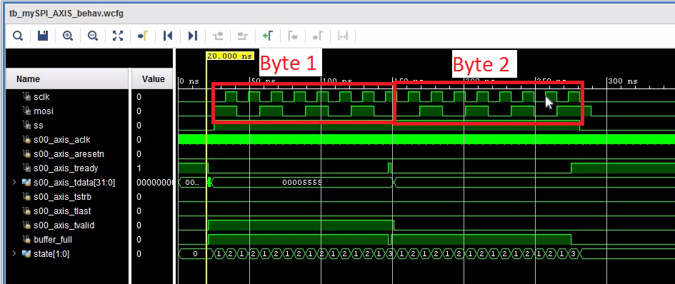
Here is the simulation result:
- Follow the instructions in this tutorial on how to create a new IP-Core. Or download the complete IP-core from the above link.
- We are using a slave AXI stream interface.
Create the Main Project
- Start with the project from this post. Or download the complete project further down.
- Locate a directory named myIPCores or SPIRxTxDemo.ipdefs/myIPCores_0 in the project directory.
- Copy the IP-Core into this directory.
- Open the block design.
- Add an AXI-Stream FIFO and configure it like this:

- Run Connection Automation.
- Add myI2STx_1.0.
- Connect the AXI stream slave interface to the axi stream master interface of the FIFO.
- Connect mclk to the corresponding output of the prescaler.
- Make bclk, lrclk, sdata external.
- Run Connection Automation.
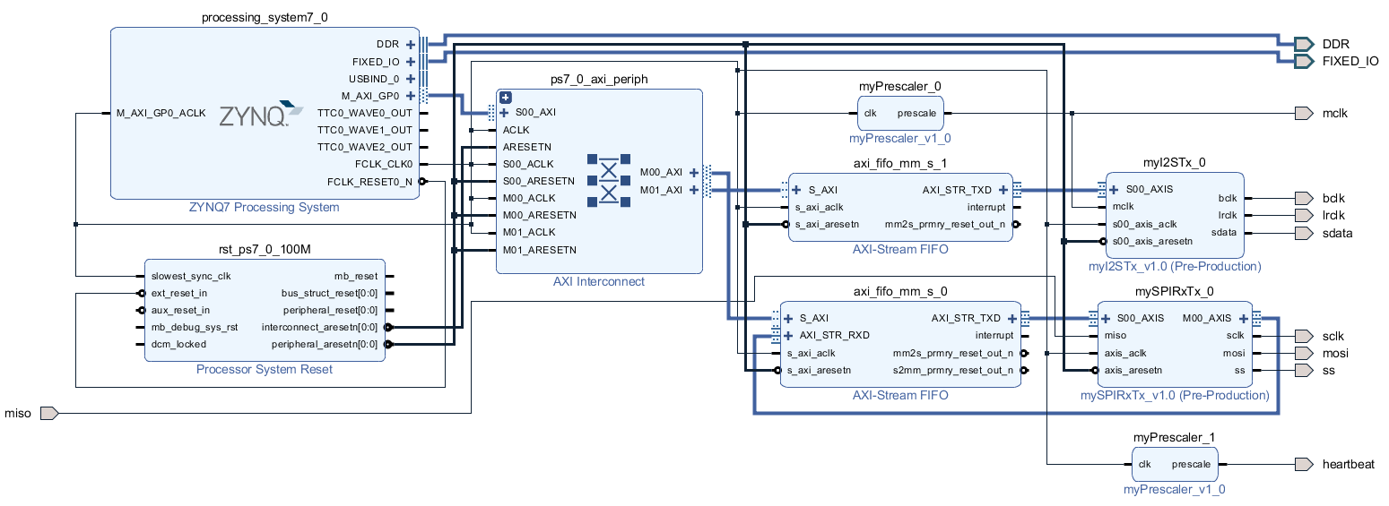
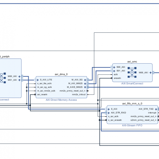
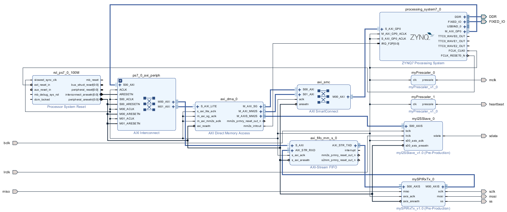
The Complete Block Design
Create the Bitstream
- Add the I2S pins to the constraints file. This is the complete constraints file:
set_property PACKAGE_PIN T22 [get_ports heartbeat]
set_property IOSTANDARD LVCMOS33 [get_ports heartbeat]

set_property PACKAGE_PIN Y5 [get_ports mosi]
set_property IOSTANDARD LVCMOS33 [get_ports mosi]
set_property PACKAGE_PIN AB5 [get_ports miso]
set_property IOSTANDARD LVCMOS33 [get_ports miso]
set_property PACKAGE_PIN AB4 [get_ports sclk]
set_property IOSTANDARD LVCMOS33 [get_ports sclk]
set_property PACKAGE_PIN AB1 [get_ports ss]
set_property IOSTANDARD LVCMOS33 [get_ports ss]
set_property PACKAGE_PIN AB2 [get_ports mclk]
set_property IOSTANDARD LVCMOS33 [get_ports mclk]

set_property PACKAGE_PIN AA6 [get_ports bclk]
set_property IOSTANDARD LVCMOS33 [get_ports bclk]
set_property PACKAGE_PIN Y6 [get_ports lrclk]
set_property IOSTANDARD LVCMOS33 [get_ports lrclk]
set_property PACKAGE_PIN Y8 [get_ports sdata]
set_property IOSTANDARD LVCMOS33 [get_ports sdata]
- Generate the bitstream.
- Open the Implementation.
- Now is a good time to launch the SDK. I encountered problems occasionally that the SDK creates a new system wrapper project. Normally there is a project named design_1_wrapper_hw_platform_0. I then have two of those. The second one named design_1_wrapper_hw_platform_1. I found the best way to resolve this was to remove both (!) projects and delete the files (you can right-click and select “Delete”). Then close SDK, export the hardware again and re-launch SDK. The project will be regenerated.
- Export Hardware (including bitstream).
Modify the C-Code
- If you haven’t done so, launch the SDK and make sure it recompiled the board-support-project.
- You might want to check if the right UART driver is selected (refer to “SDK Auto Update Bug“).
- Here is the full modified code (helloworld.c):
- Since this code uses math functions, you will have to add the “m” library to the linker settings. Go figure.
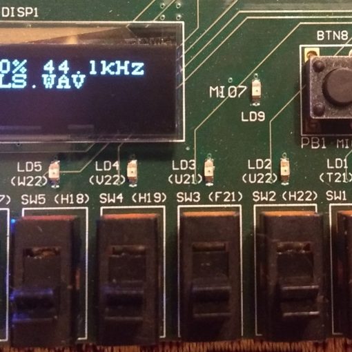
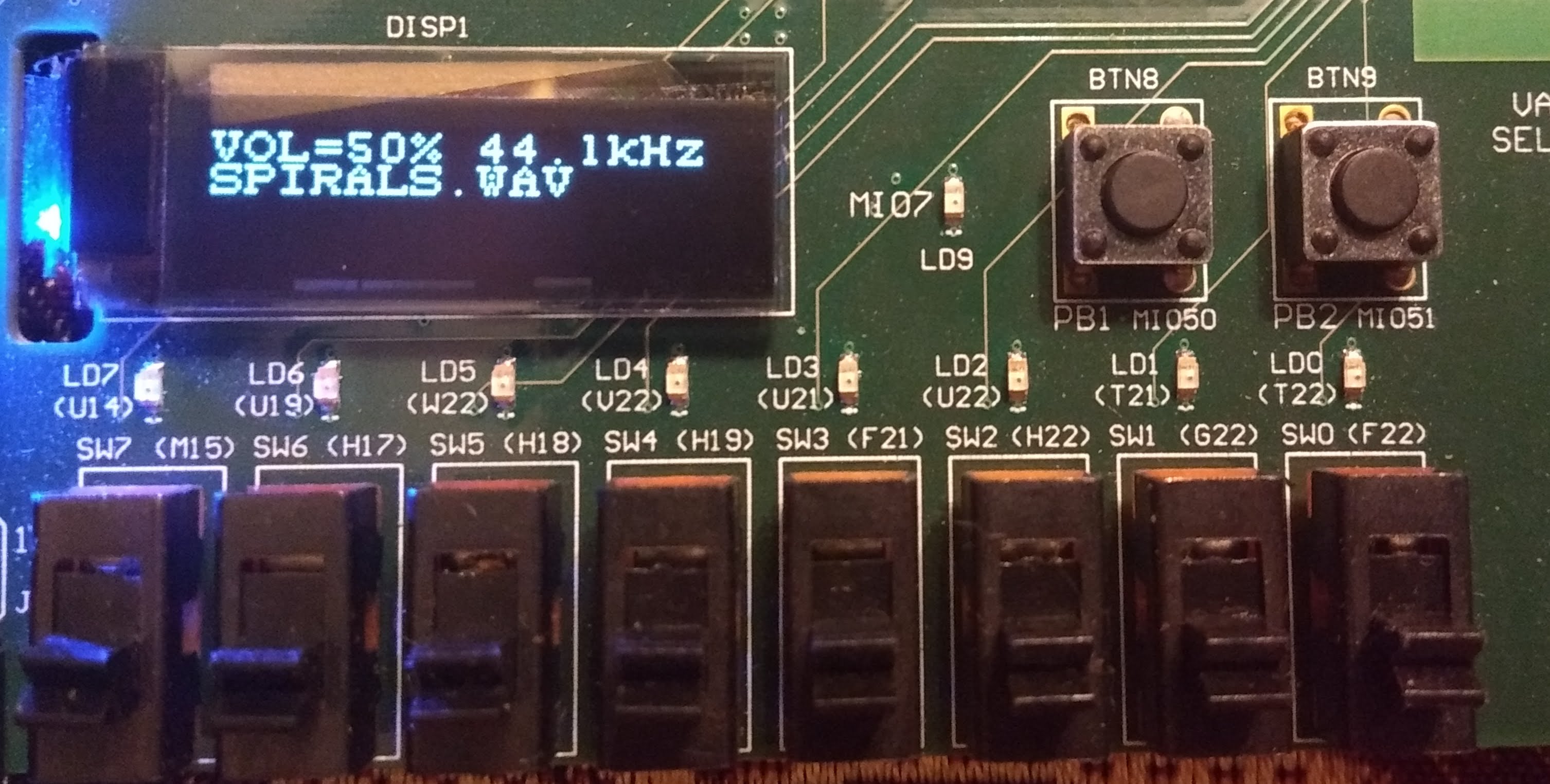
- Run the program. You should see this:
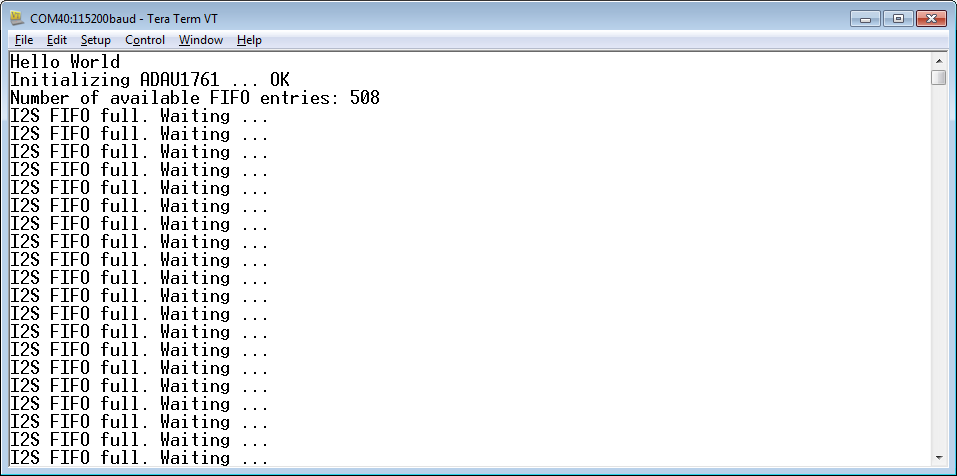
-
If you connect a speaker to the LINE output you should here a tone.
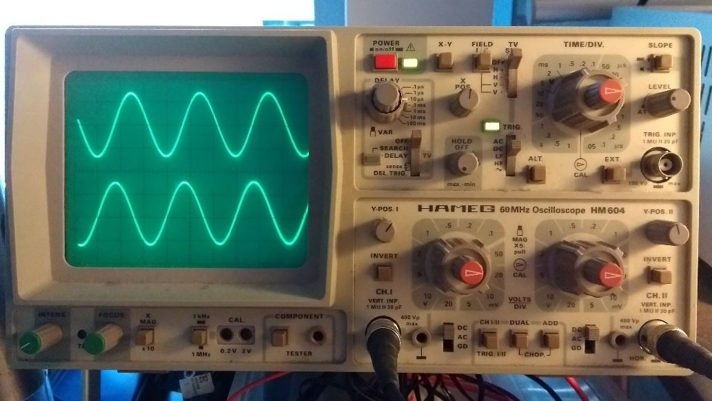
- This is how it looks on an oscilloscope (Note that the left and right channel have a phase-shift of 90 degrees):
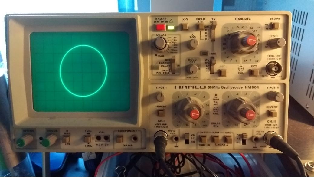
- Hence, in X/Y mode, we get a circle (almost):
Polling Mode
- In this example, we are feeding the FIFO inside a polling loop. The processor does not much more than to keep the FIFO filled.
- The FIFO has 508 entries. That means we can handle up to 13 milliseconds without feeding it.
- The next stage would be to make use of the interrupt output of the FIFO. The FIFO would then trigger an interrupt routine which keeps feeding the FIFO.
Download the Complete Project
- To upload the software to the Zedboard, open the project in Vivado, then click on “Launch SDK”.
- There seems to be a bug when updating the SDK project which selects a wrong UART driver (refer to “SDK Auto Update Bug” to fix it).
- Select the project SPIRxTxDemo and click “Run” (the “play” button at the top of the window).
Next: Interrupt-Driven Audio Output
- Learn how to use interrupts to free up the processor again.