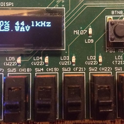
Beauty is in the eye of the beholder. Blinki is far more impressive if you know what’s under the hood…
In this tutorial we learn
- how to create a custom IP core from a Verilog file which can be used in a block diagram.
- how to assign a package pin to an output (using a constraint-file).
- how to run the FPGA without the any C-Code or the SDK (“PL without PS”).
Why is Creating an IP Core so Awkward?
I am not sure why this is such an awkward procedure. I found it hard to create an IP core from within an existing project. This is mainly because Vivado wants to package an open project into an IP core and copy it somewhere else. So you are ending up with two locations for your source code.
There is also the idea that you put all your own IP cores into a central directory on your machine (a repository). Then all your projects can use those IP cores. I found that this creates more trouble for me than it solves. I prefer to have all the IP cores I am using to be in the project sub-directory. Here is why:
- If you backup your project you will automatically include all your IP cores.
Ever made a backup of your project and forgot to backup libraries which are somewhere else? - If you are using the same IP core in multiple projects and you have to modify it for some reason, all your other projects stay unaffected.
I know people are arguing that you actually WANT your changes to propagate through to other projects. But in my experience the risk of breaking a perfectly good piece of code is much higher that way as you typically won’t have the time to test all the unrelated projects any time soon as they are by definition less important than your current one. Yes, this should be when version control should come and save the day. Except this is also not straight forward. - Compiling your project on a different machine is much easier.
Having your IP cores somewhere else than your project directory is another incarnation of the well-known dependency-hell. It is really nice if you can ZIP your project and give it to someone else without having to think about dependencies. Hint: Don’t keep your projects in your personal user directory. Put it in c:/VivadoProjects for example. This can avoid problems with absolute path names in your project (provided you copy it into the same path on the other machine).
So here is what I do:
- Create a throw-away project.
- Add your Verilog code.
- Package the project into an IP core and set as target directory the project in which you want to use it.
- Delete the throw-away project.
Let’s Create a Throw-Away Project
Add Your Own Verilog Code
module myHeartbeat(
    input clk,
    output reg heartbeat = 0
    );

    reg [24:0]divider = 0;
    always @(posedge clk) begin
        if (divider == 0) begin
            heartbeat <= !heartbeat;
        end
        divider <= divider+1;
    end
endmodule
Package as IP Core
- The top level project is going to live in c:/VivadoProjects/Blinki2
- Manually create the directory c:/VivadoProjects/Blinki2/myIPCores/myHeartbeat. This is where the new IP core is going to live.
Save IP Core
- You have the chance to edit your IP core settings.
- You can ignore the warnings.
- You can delete the DeleteMe-project after you closed it.
Create Top-Level Project
Create a Block Design
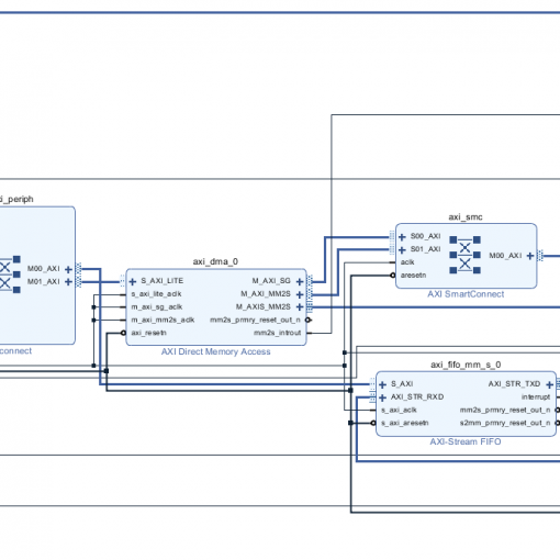
- A block-design is often the top-level FPGA code. It can be used to wire up the different logic modules (aka IP cores).
- A block design always contains the ZYNQ7 Processing System.
- Block Automation tries to guess what you want to do. Very useful, however not always correct.
- You always need to connect the clock output FCLK_CLK0 to the AXI bus M_AXI_GP0_ACLK.
Add Your Local IP Core Repository
After your local IP core directory has been added, you can add your new IP core to the block diagram.
Add Your IP Core to the Block Diagram
- We connect the clock input of the heartbeat IP core to the system clock.
- We turn the output into an external pin, so we can connect it later to a package pin.
Add a Constraints File
- Pin definitions are normally kept in a so-called Constraints-File.
Setup the Heartbeat Pin
- You will have to look up in the schematics which pin the LED is connected to. In this case it’s pin T22.
- You also need to define the logic levels. In this case it’s LVCMOS33 for 3.3V logic levels.
set_property PACKAGE_PIN T22 [get_ports heartbeat]
set_property IOSTANDARD LVCMOS33 [get_ports heartbeat]
Create the Bitstream
- Be aware that the synthesis and the implementation will take a few minutes to run.
- After the bitstream has been created, we can go directly into the Hardware Manager to upload it to the FPGA.
Upload the Bitstream
- You can upload the bitstream using the Hardware Manager, but it would not run because the PS side has not been initialized, yet.
- Continue here to learn how to initialize the PS side and to upload the bitstream.
References


One thought on “ZYNQ: Blinki (Now the FPGA does the blinking)”
Ηi, I wish for to subscribe for thіs ᴡebsіte to get most rеcent
updates, therefore whеre can i do it please help.