Now it is going to pay off that we are using an AXI interface on our I2S transmitter. We can now exchange the FIFO with a DMA controller. DMA stand for “Direct Memory Access”. The DMA controller can move data from the main memory to the AXI stream interface without bothering the CPU. This allows you to play audio data while the CPU is doing something else.
In this tutorial we learn:
- How to add an AXI DMA controller to the block design.
- How to use the “XAxiDma” driver in your C-code.
- How to set up a chain of Buffer Descriptors (BDs) to program the data flow to the audio codec.
Create the Main Project
- Start with the project from this post. Or download the complete project further down.
- Open the block design and double-click the ZYNQ Processing System. Enable an additional General Purpose Slave AXI interface:
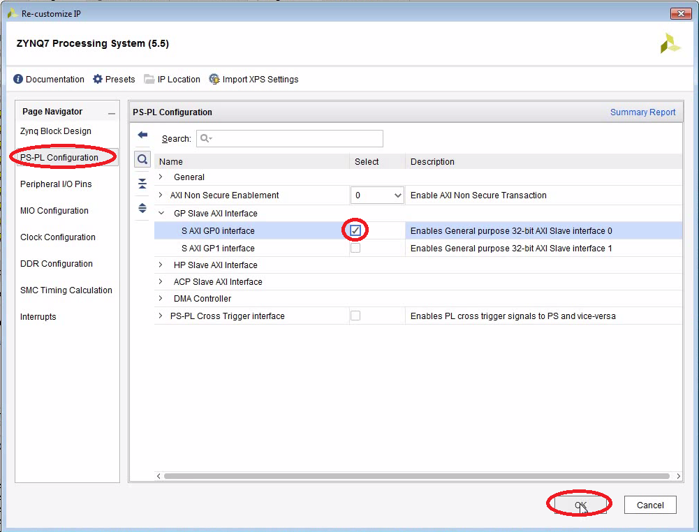
- The DMA controller uses this slave interface to get access to the DDR memory.
- Delete the AXI FIFO which is connected to the I2S interface.
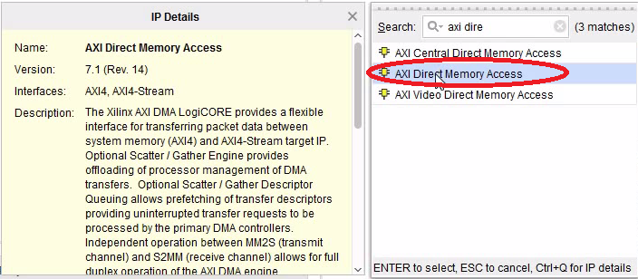
- Add an AXI Direct Memory Access IP core:
- Configure the DMA controller:
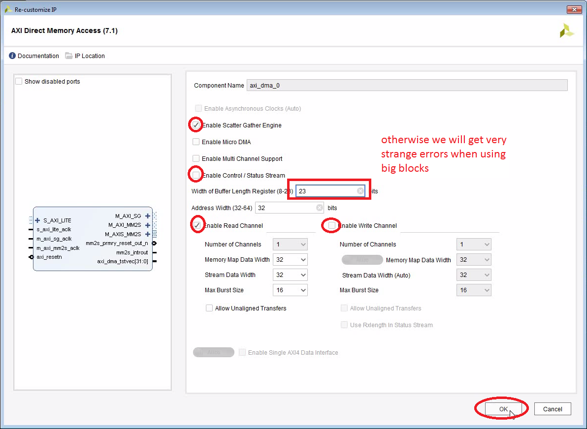
Note that the default width of the Buffer Length Register is only 16 bits. The library will not protect you from attempting to write too big blocks. Took me hours to figure that out… Better to increase it to 23 bits right from the start. - Run Connection Automation.
- Connect the remaining AXI Stream Master (M_AXIS_MM2S) to the I2S controller.
- Connect the interrupt output (mm2s_introut) to the interrupt input of the ZYNQ Processing System (IRQ_F2P[0:0]).
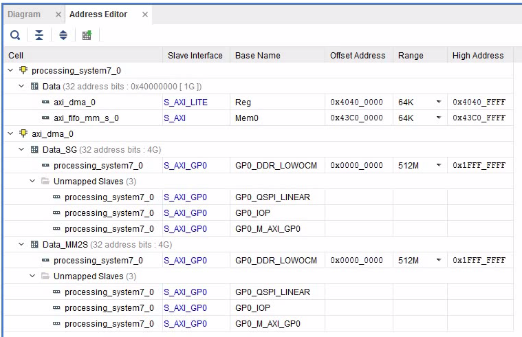
- Go to the Address Editor. You will find two memory maps. One is how the ZYNQ sees the memory space. The second memory map is how the DMA controller sees its memory space. I had problems before with those memory maps being different. So, I figure it is best to remove the unused peripherals from the memory map of the DMA controller. We only want to transfer from main DDR memory anyway. You can unmap segments by right-clicking them:
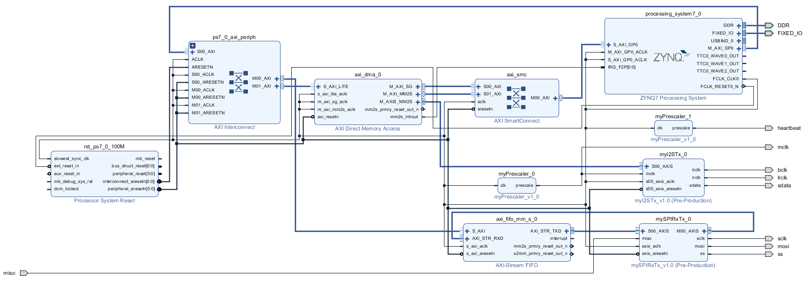
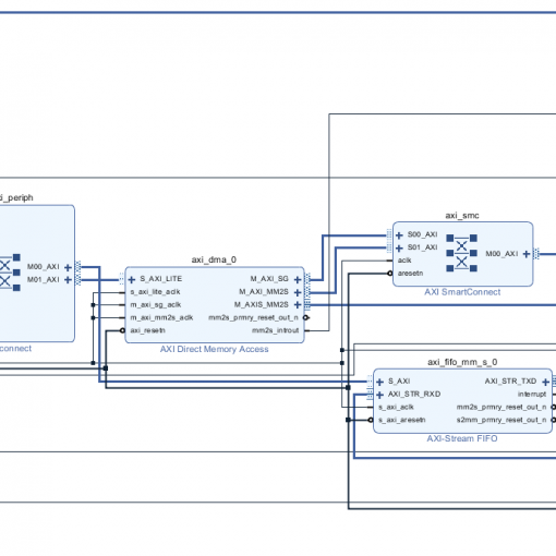
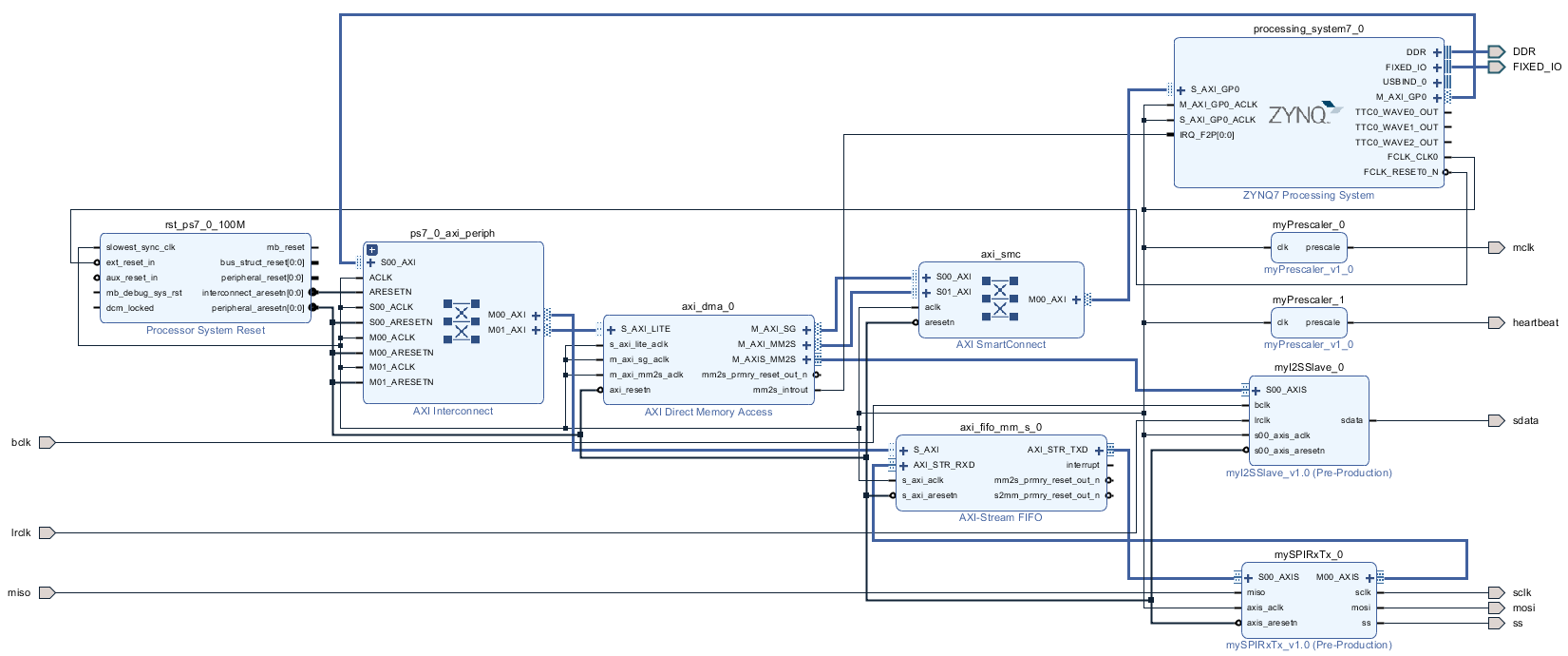
 This is how it should look like:
The Complete Block Design
Create the Bitstream
- Generate the bitstream.
- Open the Implementation.
- Now is a good time to launch the SDK. I encountered problems occasionally that the SDK creates a new system wrapper project. Normally there is a project named design_1_wrapper_hw_platform_0. I then have two of those. The second one named design_1_wrapper_hw_platform_1. I found the best way to resolve this was to remove both (!) projects and delete the files (you can right-click and select “Delete”). Then close SDK, export the hardware again and re-launch SDK. The project will be regenerated.
- Export Hardware (including bitstream).
Modify the C-Code
- If you haven’t done so, launch the SDK and make sure it recompiled the board-support-project.
- You might want to check if the right UART driver is selected (refer to “SDK Auto Update Bug“).
- Here is the full modified code (helloworld.c):

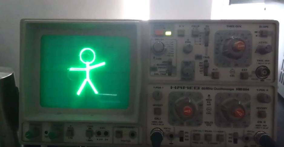
- Run the program. You should see this:
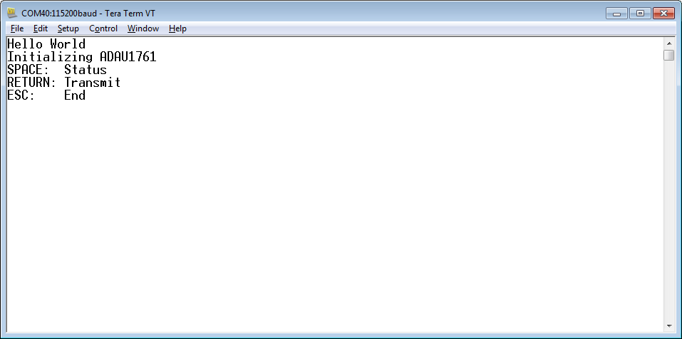
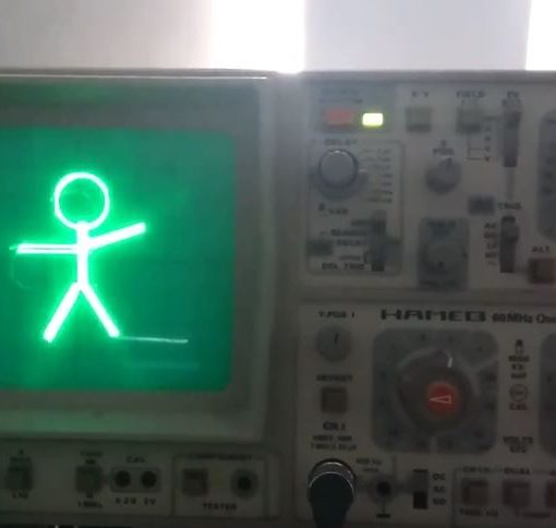
- If you connect a speaker to the LINE output and press RETURN you should here a short tone.
- Each RETURN-press adds 200 repeated sine periods into the buffer. If you keep hitting RETURN fast enough the tone will be seamlessly prolonged. If you add more than 4000 periods, the buffer will overflow and the program will complain.
- Press SPACE to display if the DMA is busy.
- Press ESC to quit and reset the DMA controller.
Basic Concept of the DMA Controller
- The DMA controller reads and interprets so-called Buffer Descriptors (BDs) to find out what to do next.
- Each BD occupies 64 bytes in memory and contains pointers to the actual memory which we want to transfer.
- BDs are chained together and form a linked list. Once a BD has been processed, the DMA controller proceeds to the next BD.
- In the C-code, we are using the axidma driver from Xilinx (look up the documentation in the bsp project).
- The initialization starts with pre-filling a fixed-size memory with a large number of BDs (use the API functions XAxiDma_BdRingCreate(), XAxiDma_BdRingClone()). XAxiDma_BdRingCreate() sets everything up so that the last BD links to the 1st. In other words, it creates a ring buffer. This will be the pool of BDs available to the API.
- Use the API function XAxiDma_BdRingStart() to hand over the BD ring buffer to the API. For some reason XAxiDma_StartBdRingHw(), as suggested in the example code, did not work for me.
- Now the ring buffer memory is maintained by the driver. Once it is handed over, you must not write into it.
- Always use the API functions XAxiDma_BdRingAlloc() and XAxiDma_BdRingToHw() to put transfers into the queue.
Download the Complete Project
- To upload the software to the Zedboard, open the project in Vivado, then click on “Launch SDK”.
- There seems to be a bug when updating the SDK project which selects a wrong UART driver (refer to “SDK Auto Update Bug” to fix it).
- Select the project SPIRxTxDemo and click “Run” (the “play” button at the top of the window).
Next: Read a WAV File from SD-Card and Play it on the Audio Codec
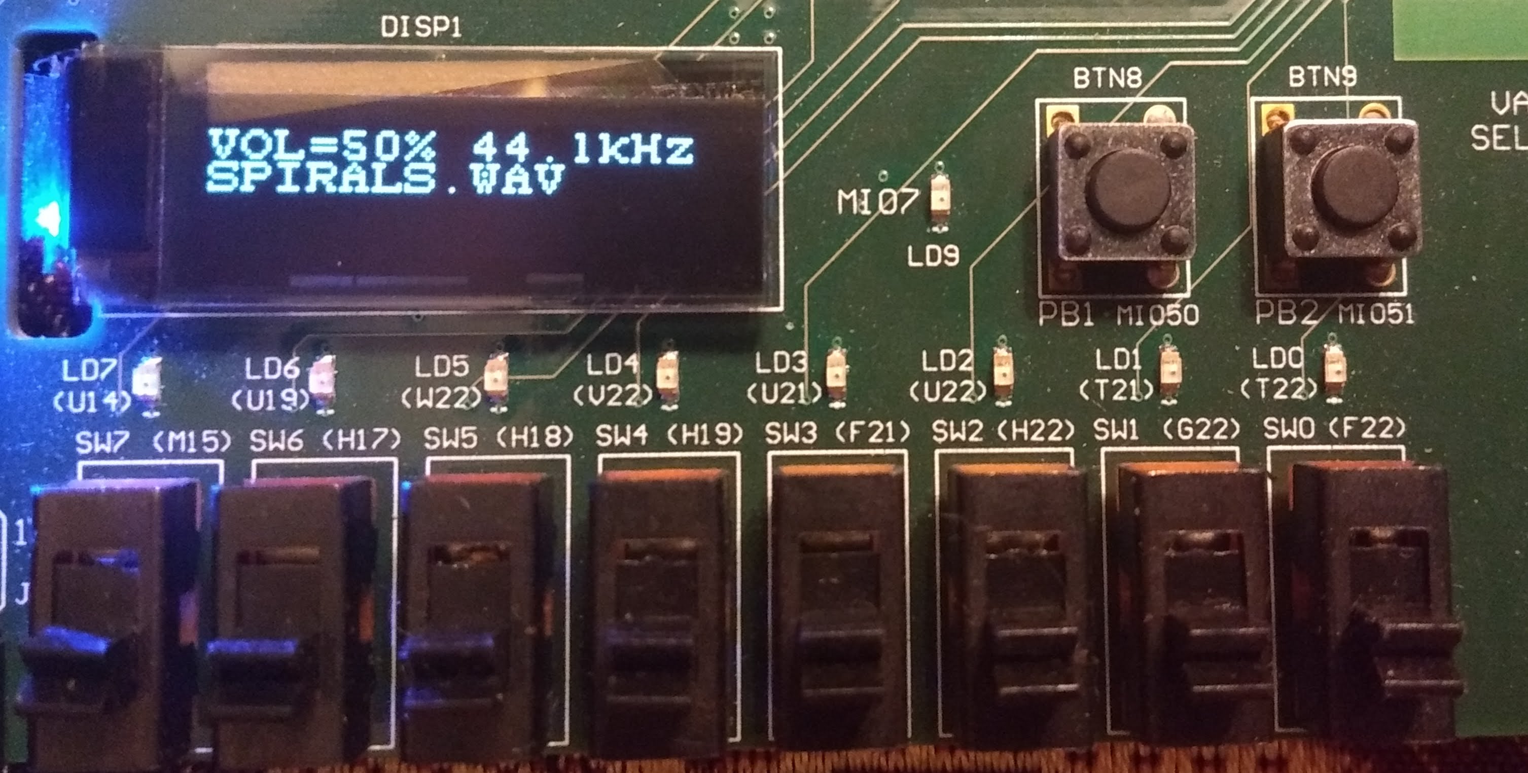
- Now we are ready to play a WAV file from the SD card.
ZYNQ: Read a WAV File from SD-Card and Play it on the Audio Codec